Sign In
Upload
Download
Table of Contents
Contents
Add to my manuals
Delete from my manuals
Share
URL of this page:
HTML Link:
Bookmark this page
Add
Manual will be automatically added to "My Manuals"
Print this page
×
Bookmark added
×
Added to my manuals
Manuals
Brands
METREL Manuals
Measuring Instruments
EurotestIM
Instruction manual
METREL EurotestIM Instruction Manual
Hide thumbs
1
2
Table Of Contents
3
4
5
6
7
8
9
10
11
12
13
14
15
16
17
18
19
20
21
22
23
24
25
26
27
28
29
30
31
32
33
34
35
36
37
38
39
40
41
42
43
44
45
46
47
48
49
50
51
52
53
54
55
56
57
58
59
60
page
of
60
Go
/
60
Contents
Table of Contents
Bookmarks
Table of Contents
Table of Contents
Preface
Safety and Operational Considerations
Warnings and Notes
Battery and Charging
Standards Applied
Instrument Description
Front Panel
Connector Panel
Back Side
Carrying the Instrument
Instrument Set and Accessories
Standard Set MI 3110
Optional Accessories
Instrument Operation
Display Organization
Terminal Voltage Monitor
Battery Indication
Messages
Results
Sound Warnings
Help Screens
Backlight and Contrast Adjustments
Function Selection
Instruments Main Menu
Settings
Memory
Language
Date and Time
Isc Factor
Commander Support
Initial Settings
Measurements - A.C. LV IT Installations
Voltage, Frequency and Phase Sequence
Line Impedance and Prospective Short-Circuit Current / Voltage Drop
Line Impedance and Prospective Short Circuit Current
Voltage Drop
First Fault Leakage Current (ISFL)
Testing of Insulation Monitoring Devices (IMD)
Automatic Measurement Procedure
PE Test Terminal
Data Handling
Memory Organization
Data Structure
Storing Test Results
Recalling Test Results
Clearing Stored Data
Clearing Complete Memory Content
Clearing Measurement(S) in Selected Location
Clearing Individual Measurements
Renaming Installation Structure Elements (Upload from PC)
Communication
Upgrading the Instrument
Maintenance
Fuse Replacement
Cleaning
Periodic Calibration
Service
Technical Specifications
Voltage, Frequency, and Phase Rotation
Voltage
Frequency
Online Terminal Voltage Monitor
Phase Rotation
Line Impedance and Prospective Short-Circuit Current / Voltage Drop
First Fault Leakage Current (ISFL)
Calibrated Resistance for IMD Testing
General Data
Appendix A - Fuse Table
Fuse Table - IPSC
Fuse Table - Impedances (UK)
Appendix B - Accessories for Specific Measurements
Appendix C - Commanders (a 1314, a 1401)
Warnings Related to Safety
Battery
Description of Commanders
Operation of Commanders
Advertisement
Quick Links
Download this manual
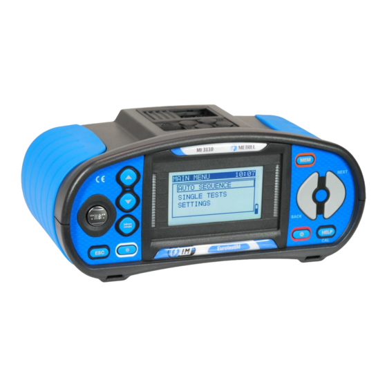
EurotestIM
MI 3110
Instruction manual
Version 1.2.2, Code no. 20 752 063
Table of
Contents
Previous
Page
Next
Page
1
2
3
4
5
Advertisement
Table of Contents
Need help?
Do you have a question about the EurotestIM and is the answer not in the manual?
Ask a question
Questions and answers
Related Manuals for METREL EurotestIM
Measuring Instruments Metrel EurotestDL Instructions Manual
(13 pages)
Measuring Instruments Metrel EurotestXC MI 3152 Instruction Manual
Eurotestxc eurotestxc 2,5 kv (203 pages)
Measuring Instruments METREL EurotestXC Quick Manual
(125 pages)
Measuring Instruments METREL EurotestPV Lite MI 3109 Instruction Manual
(75 pages)
Measuring Instruments METREL EurotestXE Instruction Manual
(114 pages)
Measuring Instruments METREL MI 3102 Short Instructions
(17 pages)
Measuring Instruments METREL MI 3110 Instruction Manual
(60 pages)
Measuring Instruments METREL PowerQ4MI 2592 Instruction Manual
(104 pages)
Measuring Instruments METREL Instaltest 61557 MI 2087 Instruction Manual
(68 pages)
Measuring Instruments METREL DeltaGT MI 3309 Instruction Manual
(82 pages)
Measuring Instruments METREL A 1378 Instruction Manual
Pv remote unit (21 pages)
Measuring Instruments METREL EurotestAT MI 3101 Short Instructions
(29 pages)
Measuring Instruments METREL MI 3103 User Manual
Gigaohm 1kv (20 pages)
Measuring Instruments METREL power master MI 2892 Instruction Manual
(164 pages)
Measuring Instruments METREL MI 3125 Instruction Manual
Instaltestcombo (60 pages)
Measuring Instruments METREL RCD MI 2120 User Manual
Loop resistance and system resistance tester (28 pages)
This manual is also suitable for:
Mi 3110
Table of Contents
Print
Rename the bookmark
Delete bookmark?
Delete from my manuals?
Login
Sign In
OR
Sign in with Facebook
Sign in with Google
Upload manual
Upload from disk
Upload from URL


Need help?
Do you have a question about the EurotestIM and is the answer not in the manual?
Questions and answers