Sign In
Upload
Download
Table of Contents
Contents
Add to my manuals
Delete from my manuals
Share
URL of this page:
HTML Link:
Bookmark this page
Add
Manual will be automatically added to "My Manuals"
Print this page
×
Bookmark added
×
Added to my manuals
Manuals
Brands
METREL Manuals
Measuring Instruments
EurotestXE
Instruction manual
METREL EurotestXE Instruction Manual
Hide thumbs
Also See for EurotestXE
:
Short instructions
(17 pages)
1
2
Table Of Contents
3
4
5
6
7
8
9
10
11
12
13
14
15
16
17
18
19
20
21
22
23
24
25
26
27
28
29
30
31
32
33
34
35
36
37
38
39
40
41
42
43
44
45
46
47
48
49
50
51
52
53
54
55
56
57
58
59
60
61
62
63
64
65
66
67
68
69
70
71
72
73
74
75
76
77
78
79
80
81
82
83
84
85
86
87
88
89
90
91
92
93
94
95
96
97
98
99
100
101
102
103
104
105
106
107
108
109
110
111
112
113
114
page
of
114
Go
/
114
Contents
Table of Contents
Bookmarks
Table of Contents
Table of Contents
Preface
Safety and Operational Considerations
Warnings and Notes
Battery and Charging
Standards Applied
Instrument Description
Front Panel
Connector Panel
Back Side
Carrying the Instrument
Instrument Set and Accessories
Standard Set MI 3102H BT - Eurotestxe
Standard Set MI 3102 BT - Eurotestxe
Optional Accessories
Instrument Operation
Display and Sound
Terminal Voltage Monitor
Battery Indication
Messages
Results
Sound Warnings
Help Screens
Backlight and Contrast Adjustments
Function Selection
Instruments Main Menu
Settings
Memory
Language
Date and Time
Earthing System (MI 3102 BT Only)
RCD Testing
Isc Factor
Commander Support
Initial Settings
Clamp Settings
Length Units
Measurements
Voltage, Frequency and Phase Sequence
Insulation Resistance
The DAR and PI Diagnostic (MI 3102H BT Only)
Resistance of Earth Connection and Equipotential Bonding
R LOWΩ, 200 Ma Resistance Measurement
Continuous Resistance Measurement with Low Current
Compensation of Test Leads Resistance
Testing Rcds
Contact Voltage (RCD Uc)
Trip-Out Time (Rcdt)
Trip-Out Current (RCD I)
RCD Auto-Test
Fault Loop Impedance and Prospective Fault Current
Line Impedance and Prospective Short-Circuit Current / Voltage Drop
Line Impedance and Prospective Short Circuit Current
Voltage Drop
Earth Resistance
Standard Earthing Resistance Measurement
Contactless Earthing Resistance Measurement (with Two Current Clamps)
Specific Earth Resistance Measurement
PE Test Terminal
Power
Harmonics
Current
First Fault Leakage Current - ISFL (MI 3102 BT Only)
Testing of Insulation Monitoring Devices - IMD (MI 3102 BT Only)
PE Conductor Resistance
Illumination
Auto-Sequences
Data Handling
Memory Organization
Data Structures
Storing Test Results
Recalling Test Results
Clearing Stored Data
Clearing Complete Memory Content
Clearing Measurement(S) in Selected Location
Clearing Individual Measurements
Renaming Installation Structure Elements (Upload from PC)
Renaming Installation Structure Elements with Serial Barcode Reader or RFID Reader
Communication
USB and RS232 Communication
Bluetooth Communication
Upgrading the Instrument
Maintenance
Fuse Replacement
Cleaning
Periodic Calibration
Service
Technical Specifications
Insulation Resistance
Diagnostic Test (MI 3102H BT Only)
Continuity
Resistance R LOW
Resistance CONTINUITY
RCD Testing
General Data
Contact Voltage RCD Uc
Trip-Out Time
Trip-Out Current
Fault Loop Impedance and Prospective Fault Current
No Disconnecting Device or FUSE Selected
RCD Selected
Line Impedance and Prospective Short-Circuit Current / Voltage Drop
PE Conductor Resistance
No RCD Selected
RCD Selected
Resistance to Earth
Standard Earthing Resistance Measurement - 3-Wire Measurement
Contactless Earthing Resistance Measurement Using Two Current Clamps
Specific Earth Resistance Measurements
Voltage, Frequency, and Phase Rotation
Phase Rotation
Voltage
Frequency
Online Terminal Voltage Monitor
TRMS Clamp Current
Power Tests
First Fault Leakage Current - ISFL (MI 3102 BT Only)
Calibrated Resistance for IMD Testing (MI 3102 BT Only)
Illumination
Illumination (Luxmeter Sensor, Type B)
Illumination (Luxmeter Sensor, Type C)
General Data
Appendix A - Fuse Table - IPSC
Appendix B - Accessories for Specific Measurements
Appendix C - Country Notes
List of Country Modifications
AT Modification - G Type RCD
Modification of the Chapter 5.5.1
Appendix D - Commanders (a 1314, a 1401)
Warnings Related to Safety
Battery
Description of Commanders
Operation of Commanders
Advertisement
Quick Links
1
Table of Contents
2
Insulation Resistance
Download this manual
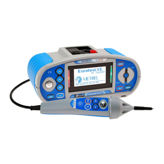
EurotestXE
MI 3102H BT
MI 3102 BT
Instruction manual
Version 1.3, Code no. 20 752 130
Table of
Contents
Previous
Page
Next
Page
1
2
3
4
5
Advertisement
Table of Contents
Need help?
Do you have a question about the EurotestXE and is the answer not in the manual?
Ask a question
Questions and answers
Related Manuals for METREL EurotestXE
Measuring Instruments METREL MI 3102 Short Instructions
(17 pages)
Measuring Instruments Metrel EurotestDL Instructions Manual
(13 pages)
Measuring Instruments Metrel EurotestXC MI 3152 Instruction Manual
Eurotestxc eurotestxc 2,5 kv (203 pages)
Measuring Instruments METREL EurotestXC Quick Manual
(125 pages)
Measuring Instruments METREL EurotestPV Lite MI 3109 Instruction Manual
(75 pages)
Measuring Instruments METREL EurotestIM Instruction Manual
(60 pages)
Measuring Instruments METREL EurotestXE MI 3102H Instruction Manual
(88 pages)
Measuring Instruments METREL MI 3102H BT Instruction Manual
(114 pages)
Measuring Instruments METREL MI 3102 BT Instruction Manual
(114 pages)
Measuring Instruments METREL PowerQ4MI 2592 Instruction Manual
(104 pages)
Measuring Instruments METREL Instaltest 61557 MI 2087 Instruction Manual
(68 pages)
Measuring Instruments METREL DeltaGT MI 3309 Instruction Manual
(82 pages)
Measuring Instruments METREL A 1378 Instruction Manual
Pv remote unit (21 pages)
Measuring Instruments METREL EurotestAT MI 3101 Short Instructions
(29 pages)
Measuring Instruments METREL MI 3103 User Manual
Gigaohm 1kv (20 pages)
Measuring Instruments METREL power master MI 2892 Instruction Manual
(164 pages)
This manual is also suitable for:
Mi 3102h bt
Mi 3102 bt
Table of Contents
Save PDF
Print
Rename the bookmark
Delete bookmark?
Delete from my manuals?
Login
Sign In
OR
Sign in with Facebook
Sign in with Google
Upload manual
Upload from disk
Upload from URL


Need help?
Do you have a question about the EurotestXE and is the answer not in the manual?
Questions and answers