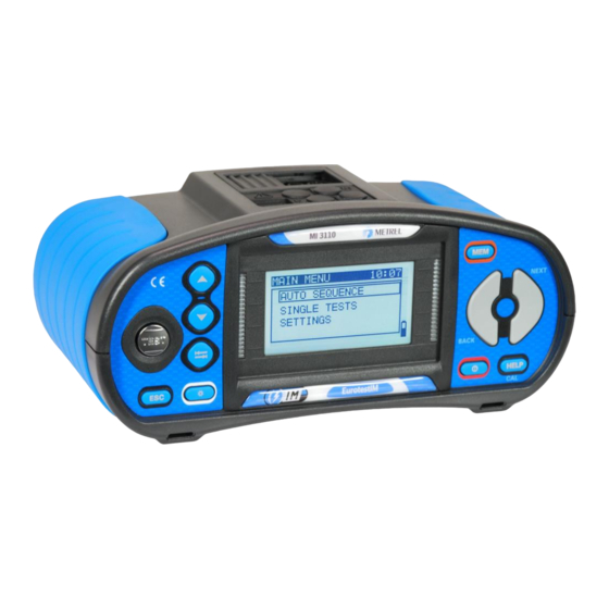
Table of Contents
Advertisement
Quick Links
Advertisement
Table of Contents

Summarization of Contents
Safety and Operational Considerations
General Safety Warnings and Notes
General safety warnings and precautions to ensure safe operation of the instrument and prevent hazards.
Battery and Charging Procedures
Information on the instrument's battery type, usage, and charging procedures for optimal performance and safety.
Applied Standards and Compliance
Details the relevant safety, EMC, and functionality standards to which the EurotestIM is manufactured and tested.
Instrument Description
Front Panel Layout and Controls
Details the components and functions of the instrument's front panel, including LCD, buttons, and indicators.
Connector Panel Overview
Illustrates and explains the various connectors and ports on the instrument for input/output and communication.
Back Side Details
Provides details on the instrument's back panel, including the battery and fuse compartment.
Carrying the Instrument
Explains the methods and options for carrying the instrument, including the use of a neck-carrying belt.
Instrument Set and Accessories
Lists standard included items and optional accessories for the MI 3110 EurotestIM instrument.
Instrument Operation
Display Organization and Indicators
Explains the instrument's display elements: voltage monitor, battery status, and message fields.
Results, Warnings, and Help Screens
Details measurement result indicators, audible alerts, and accessing help menus for guidance.
Backlight and Contrast Adjustments
Guides on adjusting the display's backlight intensity and LCD contrast for optimal visibility.
Function Selection
Explains selecting measurement functions using the instrument's selector keys.
Instrument Main Menu
Describes navigating the main menu to select test modes and access settings.
Settings Menu Options
Outlines the various instrument options that can be configured within the Settings menu.
Memory Management Settings
Guides on recalling or deleting stored measurement results and managing instrument memory.
Language and Date/Time Settings
Explains how to set the display language and configure the instrument's current date and time.
Isc Factor Configuration
Details setting the Isc factor for short circuit current calculations in Z-LINE measurements.
Commander Support Configuration
Details configuring support for external commanders (A 1314, A 1401).
Initial Settings (Factory Reset)
Guides on restoring the instrument's settings, parameters, and limits to factory default values.
Measurements – a.c. LV IT Installations
Voltage, Frequency, and Phase Sequence Measurement
Details how to measure voltage, frequency, and phase sequence in a.c. LV IT installations.
Line Impedance and Short-Circuit Current Measurement
Explains the measurement of line impedance and calculation of prospective short-circuit current.
Voltage Drop Measurement
Details the procedure for measuring voltage drop by calculating impedance difference.
First Fault Leakage Current (ISFL) Measurement
Explains how to measure the maximum current that could leak to PE during a first fault condition.
Testing Insulation Monitoring Devices (IMD)
Describes how to test IMD by applying changeable resistance and checking alarm thresholds.
Automatic Measurement Procedure
Details the auto function for performing a complete test sequence of IT supply systems.
PE Test Terminal Functionality
Explains the function and application of the PE test terminal for detecting dangerous voltages.
Data Handling
Memory Organization and Data Structure
Describes the instrument's memory structure and data organization into locations for storing results.
Storing and Recalling Test Results
Guides on how to save completed test results to memory and retrieve them later.
Clearing Stored Data
Provides instructions on clearing complete memory content or specific measurements.
Renaming Elements and PC Communication
Details renaming elements via PC and transferring data using USB or RS232 interfaces.
Maintenance
Fuse Replacement
Provides instructions and warnings for replacing the instrument's fuses, specifying type and rating.
Cleaning Procedures
Offers guidance on cleaning the instrument and accessories using appropriate methods.
Periodic Calibration
Emphasizes the importance of regular calibration for guaranteed technical specifications and recommends annual calibration.
Service and Support
Advises on contacting the distributor for repairs under warranty or other service needs.
Technical Specifications
Voltage, Frequency, and Phase Rotation Specs
Lists the technical specifications for voltage, frequency, and phase rotation measurements.
Line Impedance and Voltage Drop Specs
Details specifications for line impedance, short-circuit current, and voltage drop measurements.
ISFL and IMD Testing Specifications
Provides specifications for First Fault Leakage Current (ISFL) and IMD testing.
General Instrument Data
Presents general data about the instrument, including power, dimensions, and protection ratings.
Appendix A - Fuse Table
Fuse Table - IPSC
Provides fuse data for NV and gG types, listing rated currents and short-circuit current values.
Fuse Table - UK Impedances
Presents fuse data for UK types (B, C) with rated currents and maximum loop impedance values.
Appendix C – Commanders
Commander Safety Warnings
Details safety warnings and measuring categories for the plug and tip commanders.
Commander Battery Information
Provides information on the battery type, usage, and operating time for the commander accessories.
Commander Description and Operation
Describes commander components and explains their operation, including LED indicators and PE terminal test.


Need help?
Do you have a question about the MI 3110 and is the answer not in the manual?
Questions and answers