Table of Contents
Advertisement
Quick Links
Advertisement
Table of Contents

Related Manuals for METREL EurotestPV Lite MI 3109


Summary of Contents for METREL EurotestPV Lite MI 3109
- Page 1 EurotestPV Lite MI 3109 Instruction manual Version 1.6.2, Code no. 20 752 022...
- Page 2 (European Union) concerning safety and electromagnetic compatibility regulations © 2013 – 2017 METREL The trade names Metrel, Smartec, Eurotest, Autosequence are trademarks registered or pending in Europe and other countries. No part of this publication may be reproduced or utilized in any form or by any means...
-
Page 3: Table Of Contents
MI 3109 EurotestPV Lite Table of contents Table of contents Preface ........................5 Safety and operational considerations ..............6 Warnings and notes ..................6 Battery and charging ..................9 Standards applied ................... 11 Instrument description ..................12 Front panel ...................... 12 Connector panel .................... - Page 4 MI 3109 EurotestPV Lite Table of contents Data handling ......................53 Memory organization ..................53 Data structure ....................53 Storing test results ................... 55 Recalling test results ..................56 Clearing stored data ..................57 6.5.1 Clearing complete memory content ............... 57 6.5.2 Clearing measurement(s) in selected location ............
-
Page 5: Preface
1 Preface Congratulations on your purchase of the EurotestPV Lite instrument and its accessories from METREL. The instrument was designed on a basis of rich experience, acquired through many years of dealing with electric installation test equipment. The EurotestPV Lite instrument is a professional, multifunctional, hand-held test instrument intended to perform all measurements on photovoltaic systems. -
Page 6: Safety And Operational Considerations
2.1 Warnings and notes In order to maintain the highest level of operator safety while carrying out various tests and measurements, Metrel recommends keeping your EurotestPV Lite instrument in good condition and undamaged. When using the instrument, consider the following... - Page 7 Users must be skilled to disconnect the PV system safely in this case. Use only dedicated measuring accessories for testing on PV electrical installations. Metrel accessories for PV installations have yellow marked connectors. Consider that protection category of some accessories is lower than of the ...
- Page 8 MI 3109 EurotestPV Lite Safety and operational considerations Continuity functions Continuity measurements should only be performed on de-energized objects! Notes related to measurement functions: General PASS / FAIL indication is enabled when limit is set. Apply appropriate limit value ...
-
Page 9: Battery And Charging
MI 3109 EurotestPV Lite Safety and operational considerations 2.2 Battery and charging The instrument uses six AA size alkaline or rechargeable Ni-MH battery cells. Nominal operating time is declared for cells with nominal capacity of 2100 mAh. Battery condition is always displayed in the lower right display part. In case the battery is too weak the instrument indicates this as shown in figure 2.1. - Page 10 (more than 6 months). In this case Metrel recommends repeating the charge / discharge cycle at least 2-4 times. If no improvement is achieved after several charge / discharge cycles, then each ...
-
Page 11: Standards Applied
MI 3109 EurotestPV Lite Safety and operational considerations 2.3 Standards applied The EurotestPV Lite instruments are manufactured and tested in accordance with the following regulations: Electromagnetic compatibility (EMC) EN 61326 Electrical equipment for measurement, control and laboratory use – EMC requirements Class B (Hand-held equipment used in controlled EM environments) Safety (LVD) EN 61010-1... -
Page 12: Instrument Description
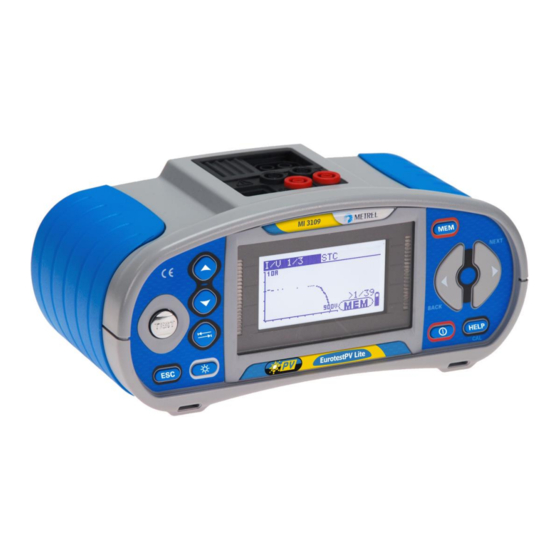
MI 3109 EurotestPV Lite Instrument description 3 Instrument description 3.1 Front panel Figure 3.1: Front panel Legend: 1 LCD 128 x 64 dots matrix display with backlight. 2 Modifies selected parameter. 3 4 TEST Starts measurements. 5 ESC Goes one level back. -
Page 13: Connector Panel
MI 3109 EurotestPV Lite Instrument description 3.2 Connector panel Figure 3.2: Connector panel Legend: Test connector Measuring inputs / outputs Charger socket USB connector Communication with PC USB (1.1) port. Protection cover Current clamp measuring input #1 Current clamp measuring input #2 P/C2 Measuring input for external probes Communication with PC serial port... -
Page 14: Back Side
MI 3109 EurotestPV Lite Instrument description 3.3 Back side Figure 3.3: Back panel Legend: Battery / fuse compartment cover Back panel information label Fixing screws for battery / fuse compartment cover Figure 3.4: Battery and fuse compartment Legend: Fuse F2, F3 FF 315 mA / 1000 V d.c. -
Page 15: Instrument Set And Accessories
Ljubljanska 77 SI - 1354 Horjul Phase rotation (EN 61557-7) Tel: +386 1 75 58 200 Nominal voltage: 100V 440V / 1 http://www.metrel.si Results: 1.2.3 or 2.1.3 Figure 3.5: Bottom Legend: Bottom information label Neck belt openings Handling side covers 3.4 Instrument set and accessories... -
Page 16: Optional Accessories
MI 3109 EurotestPV Lite Instrument description 3.4.2 Optional accessories See the attached sheet for a list of optional accessories that are available on request from your distributor. -
Page 17: Instrument Operation
MI 3109 EurotestPV Lite Instrument operation 4 Instrument operation 4.1 Display and sound 4.1.1 Warnings The A 1384 PV Safety Probe should be used for the selected test. Refer to chapter 4.4.8 Accessories for more information about use of A 1384. The conditions on measuring inputs do not allow continuing the test. -
Page 18: Results
MI 3109 EurotestPV Lite Instrument operation Warning! High voltage is applied to the test terminals. Test leads resistance in Continuity measurement is not compensated. Test leads resistance in Continuity measurement is compensated. Too small current for declared accuracy. Results may be impaired. Check in Current Clamp Settings if sensitivity of current clamp can be increased. -
Page 19: Backlight And Contrast Adjustments
MI 3109 EurotestPV Lite Instrument operation 4.1.6 Backlight and contrast adjustments With the BACKLIGHT key backlight and contrast can be adjusted. Click Toggles backlight intensity level. Locks high intensity backlight level until power is turned off or the Keep pressed for 1 s key is pressed again. -
Page 20: Instruments Main Menu
MI 3109 EurotestPV Lite Instrument operation General rule regarding enabling parameters for evaluation of measurement / test result: No limit values, indication: _ _ _. Value(s) – results will be marked as PASS or FAIL in Parameter accordance with selected limit. See Chapter 5 for more information about the operation of the instrument test functions. -
Page 21: Memory
MI 3109 EurotestPV Lite Instrument operation 4.4.1 Memory In this menu the stored data can be recalled or deleted. See chapter 8 Data handling for more information. Figure 4.5: Memory options Keys: / Selects option. TEST Enters selected option. Exits back to settings menu. -
Page 22: Initial Settings
MI 3109 EurotestPV Lite Instrument operation 4.4.4 Initial settings In this menu the instrument settings, measurement parameters and limits can be set to initial (factory) values. Figure 4.8: Initial settings dialogue Keys: / Selects option [YES, NO]. TEST Restores default settings (if YES is selected). -
Page 23: Clamp Settings
MI 3109 EurotestPV Lite Instrument operation 4.4.5 Clamp Settings In Clamp settings menu the C1 and C2/P measuring inputs can be configured. Figure 4.9: Configuration of current clamp measuring inputs Parameters to be set: Model Model of current clamp [A 1018, A 1019, A 1391]. Range Measuring range of current clamp [20 A, 200 A], [40 A, 300 A]. - Page 24 MI 3109 EurotestPV Lite Instrument operation Synchronization (of time stamps) enables to later update the PV measured results with environmental data that were measured simultaneously with the A 1378 PV Remote unit. Stored STC values are then corrected accordingly. Selecting this option will allow synchronization of data between the instrument and PV Remote unit.
-
Page 25: Solar Settings
MI 3109 EurotestPV Lite Instrument operation 4.4.7 Solar settings In Solar settings parameters of PV modules and settings for PV measurements can be set. Figure 4.12: Solar settings Keys: / Selects option. TEST Enters menu for changing parameters. Exits back to settings menu. - Page 26 MI 3109 EurotestPV Lite Instrument operation Selection of PV module type and parameters Keys: / Selects appropriate option. TEST Enters menu for changing type or parameters. ESC, Function selector Exits back. Enters PV module type memory menu. Changing a PV module type / parameter Keys: ...
- Page 27 MI 3109 EurotestPV Lite Instrument operation Figure 4.15: Delete options Keys: TEST Confirms clearing. In Delete all option YES must be selected. Exits back to PV module type memory menu without changes. Function selector Exits back to main function menu without changes. PV measurements settings Parameters for PV measurements can be set in this menu.
-
Page 28: Accessories
MI 3109 EurotestPV Lite Instrument operation Changing data of selected parameter Keys: / Sets parameter. TEST Confirms set data. ESC / Function selector Exits back. 4.4.8 Accessories In the Accessories menu options for demanded accessories can be set. Figure 4.17: Accessories menu Options are: TEST CABLE... - Page 29 EurotestPV Lite instrument In the BLUETOOTH DEVICES menu a Metrel Powermeter with Bluetooth connection can be found, selected and paired with the instrument. The Metrel Powermeter must have connected a properly initialized Bluetooth dongle A 1436. See chapter Initialization of the Bluetooth dongle(s) for more details.
- Page 30 MI 3109 EurotestPV Lite Instrument operation Figure 4.21: Searching and selection of Metrel Powermeter Bluetooth connection Keys: UP / DOWN Selects appropriate Bluetooth device. TEST Confirms selected device. Exits back to Bluetooth devices menu. Function selector Exits back to main menu without changes.
- Page 31 MI 3109 EurotestPV Lite Instrument operation Initialization procedure (Bluetooth dongle for the Metrel Powermeter): 1. Connect Bluetooth dongle A 1436 (intended to be used with the Metrel Powermeter) to the EurotestPV Lite instrument’s PS/2 port. 2. Switch on the EurotestPV Lite instrument.
-
Page 32: Measurements
MI 3109 EurotestPV Lite Measurements 5 Measurements 5.1 Insulation resistance The Insulation resistance measurement is performed in order to ensure safety against electric shock through insulation between live parts on PV installations and earth. The measurement is carried out according to test method 1 in IEC / EN 62446 (test between panel / string / array negative and earth followed by a test between panel / string / array positive and earth). - Page 33 MI 3109 EurotestPV Lite Measurements Figure 5.3: Connection for insulation measurement with PV Safety Probe Insulation resistance measuring procedure sub-function using the function selector keys and / keys. Select the Roc- Set the required test voltage. Enable and set limit value (optional).
-
Page 34: Resistance Of Earth Connection And Equipotential Bonding
MI 3109 EurotestPV Lite Measurements 5.2 Resistance of earth connection and equipotential bonding The resistance measurement is performed in order to ensure that the protective measures against electric shock through earth connections and bondings are effective. Two sub-functions are available: R LOWΩ... -
Page 35: Continuous Resistance Measurement With Low Current
MI 3109 EurotestPV Lite Measurements R LOWΩ measurement procedure Select continuity function using the function selector keys. R LOWΩ using / keys. Set sub-function to Enable and set limit (optional). Connect PV continuity test lead to the instrument. ... -
Page 36: Compensation Of Test Leads Resistance
MI 3109 EurotestPV Lite Measurements Connect PV continuity test lead to the instrument. Compensate test leads resistance (if necessary, see section 5.2.3). Disconnect from mains supply and discharge the object to be tested. Connect test leads to the tested object (see Figure 5.8). ... -
Page 37: Pv Inverter Test
For 3-phase inverters one DC and three AC signals can be measured at the same time with a combination of a Metrel Powermeter and the EurotestPV Lite instrument. During the measurement the Power meter and EurotestPV Lite instrument must be connected via serial cable or Bluetooth link. - Page 38 MI 3109 EurotestPV Lite Measurements Connection for PV inverter measurement Figure 5.15: Connection with universal PV test lead – DC side Figure 5.16: Connection with universal PV test lead – AC side Figure 5.17: Connection with PV Safety Probe - DC side...
- Page 39 MI 3109 EurotestPV Lite Measurements Figure 5.18: Connection with PV Safety Probe - AC side Figure 5.19: Connection with A 1385 - AC and DC sides Figure 5.20: Connection to Metrel Powermeter for 3 phase AC measurements...
- Page 40 Connect accessories to the PV system (see figures 5.15 to 5.19). Check input voltages. Press the TEST key to perform the measurement. Store the result by pressing the MEM key (optional). PV inverter test procedure (with EurotestPV Lite instrument and Metrel Powermeter)
- Page 41 MI 3109 EurotestPV Lite Measurements Note: The Communication settings of Powermeter must be following: Source = RS232 Baud Rate = 9600 sub-function using the function selector keys and / keys. Select INVERTER Be sure that the EurotestPV Lite instrument and Powermeter are connected via ...
-
Page 42: Pv Panel Test
For the INVERTER AC/DC test fused test lead A 1385 must be used! For more information about measuring and setup of the Metrel Powermeter refer to Metrel Powermeter’s instruction manual. Contact Metrel or distributor for detailed... - Page 43 MI 3109 EurotestPV Lite Measurements Connection for PV panel test Figure 5.27: Connection with universal PV test lead Figure 5.28: Connection with PV safety probe PV panel test procedure Select PANEL sub-function using the function selector keys. Connect universal PV test lead / PV safety probe, current clamp(s) and sensors ...
-
Page 44: Measuring Of Environmental Parameters
MI 3109 EurotestPV Lite Measurements Figure 5.29: Examples of PV measurement results Displayed results are: MEAS column U....measured output voltage of the panel I ....measured output current of the panel P ....measured output power of the panel STC column U.... - Page 45 MI 3109 EurotestPV Lite Measurements See chapter 4.2 Function selection for instructions on key functionality. Figure 5.30: Environmental parameters screen Test parameters for measuring / setting of environmental parameters INPUT Input of environmental data [ MEAS, MANUAL] OTHER Shortcut to SOLAR SETTINGS menu Connection for measuring of environmental parameters Figure 5.31: Measurement of environmental parameters Procedure for measuring of environmental parameters...
-
Page 46: Operation With A 1378 Pv Remote Unit
MI 3109 EurotestPV Lite Measurements If the data is measured with other measuring equipment they can be entered manually. Select ENV. function and MANUAL sub-function using the function selector keys and Up/Down keys. Keys: TEST Enters menu for manual setting of environmental parameters. Enters menu for changing selected parameter. - Page 47 MI 3109 EurotestPV Lite Measurements Connection for Uoc / Isc measurement Figure 5.35: Connection with universal PV test lead Figure 5.36: Connection with PV safety probe Uoc / Isc measurement procedure sub-function using the function selector keys and / keys. Select Uoc / Isc ...
-
Page 48: I / V Curve Measurement
MI 3109 EurotestPV Lite Measurements Isc.... measured short circuit current of the panel STC column Uoc ..calculated open voltage at STC Isc.... calculated short circuit current at STC U:..... actual voltage on test inputs Notes: Before starting the PV measurements settings of PV module type and PV test ... - Page 49 MI 3109 EurotestPV Lite Measurements Connection for the I / V curve measurement Figure 5.39: Connection with universal PV test lead Figure 5.40: Connections with PV safety probe I / V curve measurement procedure sub-function using the function selector keys and / keys. Select I / V ...
-
Page 50: Automatic Measurement Procedure According To Iec/ En 62446 (Auto)
MI 3109 EurotestPV Lite Measurements Displayed results for I / V curve test: Uoc ..measured / STC open circuit voltage of the panel Isc.... measured / STC short circuit current of the panel Umpp ..measured / STC voltage at maximal power point Impp .. - Page 51 MI 3109 EurotestPV Lite Measurements Test circuits for automatic measurement Figure 5.43: Connection for automatic measurement with universal PV test lead Automatic measurement procedure Select AUTOTEST mode from main menu. Set environmental parameters, module and measuring settings (optional). Select the AUTO sub-function using the function selector keys.
-
Page 52: Measurement Of Cell Temperature Before Test
MI 3109 EurotestPV Lite Measurements Notes: Before starting the PV measurements settings of PV module type and PV test parameters should be checked. For calculation of STC results correct PV module type, PV test parameters, Irr and Tcell values must be measured or be entered manually before the test. The Irr and T results in ENV. -
Page 53: Data Handling
MI 3109 EurotestPV Lite Data handling 6 Data handling 6.1 Memory organization Measurement results together with all relevant parameters can be stored in the instrument’s memory. After the measurement is completed, results can be stored to the flash memory of the instrument, together with the sub-results and function parameters. 6.2 Data structure The instrument’s memory place is divided into 4 levels each containing 199 locations. - Page 54 MI 3109 EurotestPV Lite Data handling level: PANEL: Default location name (panel and its successive number). 001: No. of selected element. No. of measurements in selected location [No. of measurements in selected location and its sub- locations] Measurement field Type of stored measurement in the selected location.
-
Page 55: Storing Test Results
MI 3109 EurotestPV Lite Data handling 6.3 Storing test results After the completion of a test the results and parameters are ready for storing ( icon is displayed in the information field). By pressing the MEM key, the user can store the results. -
Page 56: Recalling Test Results
MI 3109 EurotestPV Lite Data handling 6.4 Recalling test results Press the MEM key in a main function menu when there is no result available for storing or select MEMORY in the SETTINGS menu. Figure 6.3: Recall menu - installation Figure 6.4: Recall menu - measurements structure field selected field selected... -
Page 57: Clearing Stored Data
MI 3109 EurotestPV Lite Data handling 6.5 Clearing stored data 6.5.1 Clearing complete memory content Select CLEAR ALL MEMORY in MEMORY menu. A warning will be displayed. Figure 6.6: Clear all memory Keys in clear all memory menu TEST Confirms clearing of complete memory content (YES must be selected with ... -
Page 58: Clearing Individual Measurements
MI 3109 EurotestPV Lite Data handling Exits back to delete results menu (installation structure field MEM / ESC selected) without changes. Function selector Exits back to main menu without changes. 6.5.3 Clearing individual measurements Select DELETE RESULTS in MEMORY menu. Figure 6.9: Menu for clearing individual measurement (installation structure field selected) Keys in delete results menu (installation structure field selected):... -
Page 59: Renaming Installation Structure Elements (Upload From Pc)
A new location name (scanned from a barcode label or a RFID tag) will be accepted by the instrument. A successful receive of a barcode or RFID tag is confirmed by two short confirmation beeps. Note: Use only barcode readers and RFID readers delivered by Metrel or authorized distributor. -
Page 60: Communication
MI 3109 EurotestPV Lite Data handling 6.6 Communication There are two communication interfaces available on the instrument: USB or RS 232. With the optional Bluetooth dongle A 1436 the instrument can communicate via Bluetooth too. 6.6.1 USB and RS232 communication The instrument automatically selects the communication mode according to detected interface. -
Page 61: Bluetooth Communication
properly initialized. If not the Bluetooth dongle must be initialized as described in chapter 4.4.9 Communication. Switch On the Metrel Powermeter. A second Bluetooth dongle A 1436 should be inserted to the Powermeter’s PS/2 port. Be sure that the second Bluetooth dongle A 1436 is properly initialized (as ... - Page 62 MI 3109 EurotestPV Lite Data handling Notes: Sometimes there will be a demand from the PC or Android device to enter the code. Enter code ‘NNNN’ to correctly configure the Bluetooth link. The name of a correctly configured Bluetooth device must consist of the ...
-
Page 63: Upgrading The Instrument
MI 3109 EurotestPV Lite Upgrading the instrument 7 Upgrading the instrument The instrument can be upgraded from a PC via the RS232 communication port. This enables to keep the instrument up to date even if the standards or regulations change. The upgrade can be carried with a help of special upgrading software and the communication cable as shown on Figure 6.14. -
Page 64: Maintenance
MI 3109 EurotestPV Lite Maintenance 8 Maintenance Unauthorized persons are not allowed to open the EurotestPV Lite instrument. There are no user replaceable components inside the instrument, except the battery and fuses under rear cover. 8.1 Fuse replacement There are two fuses under the back cover of the EurotestPV instrument. F2, F3 FF 315 mA / 1000 V d.c. -
Page 65: Technical Specifications
MI 3109 EurotestPV Lite Technical specifications 9 Technical specifications 9.1 Insulation resistance (of PV systems) R and R Insulation resistance (nominal voltages 50 V , 100 V and 250 V Measuring range according to EN61557 is 0.15 M 199.9 M. Accuracy Measuring range (M) Resolution (M) -
Page 66: Continuity
MI 3109 EurotestPV Lite Technical specifications 9.2 Continuity 9.2.1 Resistance R LOW Measuring range according to EN61557 is 0.16 1999 . Accuracy Measuring range R () Resolution () 0.00 19.99 (3 % of reading + 3 digits) 0.01 20.0 ... -
Page 67: Pv Tests
MI 3109 EurotestPV Lite Technical specifications 9.3 PV tests 9.3.1 Accuracy of STC data Accuracy of STC values is based on accuracy of measured electrical quantities, accuracy of environmental parameters, and entered parameters of PV module. See Appendix E: PV measurements – calculated values for more information about calculation of STC values. -
Page 68: I-V Curve
For measuring range, resolution and accuracy of the 3-phase a.c. powers (Pt, P1, P2 and P3) in AC3 and AC3/DC inverter sub-functions refer to technical specifications of applied Metrel Powermeter. 9.3.3 I-V curve DC Voltage Measuring range (V) -
Page 69: Environmental Parameters
MI 3109 EurotestPV Lite Technical specifications 9.3.5 Environmental parameters Solar Irradiance Probe A 1399 Measuring range (W/m Resolution (W/m Accuracy 300 999 (5 % of reading + 5 digits) 1000 1999 5 % of reading Measuring principle: Pyranometer Operation conditions: Working temperature range .... -
Page 70: General Data
MI 3109 EurotestPV Lite Technical specifications 9.5 General data Power supply voltage ......9 V (61.5 V battery or accu, size AA) Operation .......... typical 20 h Charger socket input voltage .... 12 V 10 % Charger socket input current .... 400 mA max. Battery charging current .... -
Page 71: Appendix B - Accessories For Specific Measurements
Appendix B – Accessories for specific measurements MI 3109 EurotestPV Lite Appendix B - Accessories for specific measurements The table below presents recommended standard and optional accessories required for specific measurement. Please see attached list of standard accessories for your set or contact your distributor for further information. -
Page 72: Appendix E - Pv Measurements - Calculated Values
Appendix E – PV measurements – calculated values MI 3109 EurotestPV Lite Appendix E – PV measurements - calculated values Calculation with known U, I (DC, AC), configuration of modules into a string (M - modules in serial, N - modules in parallel), environment parameters (Irr, T) and data supplied by the panels manufacturer (U, I (AC, DC), phase, Istc, α, β, γ, Pnom, NOCT, Irr, Irr , Tamb or Tcell) - Page 73 Appendix E – PV measurements – calculated values MI 3109 EurotestPV Lite Ptheo Theoretical power of string at measured irradiance Pnom nominal power of panel at STC nominal irradiance at STC (Irr = 1000 W/m measured irradiance number of modules in serial number of modules in parallel Depending on temperature criterion for PASS is: ...
- Page 74 Appendix E – PV measurements – calculated values MI 3109 EurotestPV Lite Panel: Measured U and I are corrected to STC conditions: meas meas meas ...
- Page 75 Appendix E – PV measurements – calculated values MI 3109 EurotestPV Lite Insulation measurements of PV modules and strings The first insulation method described in the standard IEC 62446 results in two values: insulation resistance between positive output and earth insulation resistance between negative output and earth The second method described in the standard returns only one value: insulation resistance between short circuit outputs and earth...
Need help?
Do you have a question about the EurotestPV Lite MI 3109 and is the answer not in the manual?
Questions and answers