
Related Manuals for METREL EurotestDL


Summary of Contents for METREL EurotestDL
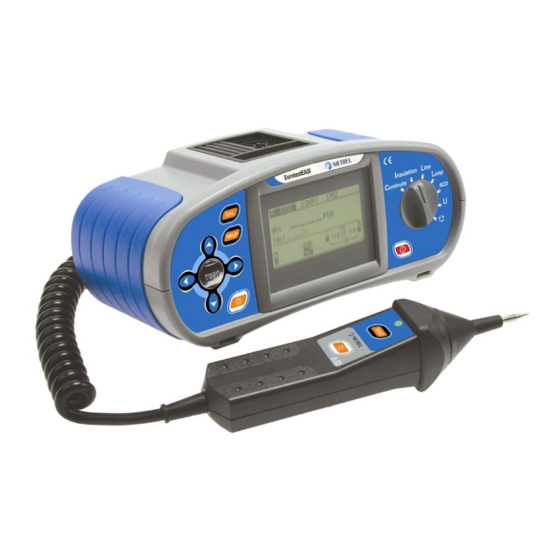
- Page 1 EurotestDL MI 3002 EurotestEASI MI 3100 Short instructions Version 2.3 UK, Code No. 20 750 114...
- Page 2 Mark on your equipment certifies that this equipment meets the requirements of the EU (European Union) concerning safety and interference causing equipment regulations © 2009 METREL No part of this publication may be reproduced or utilized in any form or by any means without permission in writing from METREL.
-
Page 3: Safety And Operational Considerations
Safety and operational considerations 1 Safety and operational considerations 1.1 Warnings • This document is a supplement to the Instruction manual! • Before using EurotestEASI instrument read the Instruction manual carefully, otherwise use of the instrument may be dangerous for the operator, for the instrument or for equipment under test! •... -
Page 4: Battery Handling
Safety and operational considerations 1.2 Battery handling • When battery cells have to be replaced or before opening battery/fuse compartment cover, disconnect any measuring accessory connected to the instrument and power off the instrument, hazardous voltage inside! • Insert cells correctly, otherwise the instrument will not operate and the battery could be discharged. - Page 5 Measurements Continuity 3 Measurements 3.1 Continuity Set function Set sub-function Set parameters and limits High limit resistance LowΩ [∗Ω sets limit off, 0.1 Ω ÷ Continuity 20.0 Ω] Connection diagram Continuity LowΩ MPEC..Main Potential Equilizing Collector PCC..Protection Conductor Collector PCC3 L/L1 PCC1 PCC2...
-
Page 6: Insulation Resistance
Measurements Insulation resistance 3.2 Insulation resistance Set function Set parameters and limits Nominal test voltage ÷ 1000 V [100 V Low limit resistance value [∗Ω sets limit off, 0.01 MΩ ÷ 200 MΩ] Connection diagram switched off closed mains voltage switches TEST Press and hold the... - Page 7 Measurements Line impedance and PSC 3.3 Line impedance (phase-neutral, phase-phase) Set function Set parameters and limits Fuse type [∗F sets limit off, BS88, BS3036, BS1361, BS1362, B, C, D] Fuse current rating [6 A ÷ 200 A] Fuse tripping time [0.4 s, 5 s] Connection diagram TEST Press the...
- Page 8 Measurements Fault loop impedance and PFC 3.4 Fault loop impedance Set function Set sub-function Set parameters and limits Fuse type [∗F sets limit off, Zs (rcd) BS88, BS3036, BS1361, BS1362, B, C, D] Fuse current rating [6 A ÷ 200 A] Fuse tripping time [0.4 s, 5 s] Connection diagram...
-
Page 9: Rcd Testing
Measurements RCD testing 3.5 RCD testing Set function Set sub-function Set parameters and limits Contact voltage Limit contact voltage [25V, Tripping time 50V] Tripping current Nominal differential RCD RCD autotest tripping current [10 mA ÷ 1000 mA] Multiplier of nominal differential RCD tripping current [×½, ×1, ×2, ×5] Test current starting polarity... -
Page 10: Voltage And Frequency
Measurements Voltage and frequency 3.6 Voltage and frequency Set function Connection diagram View results Displayed results: Ul(1)-n(2): Voltage between phase and neutral conductors (or between phases L1 and L2) Ul(1)-pe(3): Voltage between phase and protective conductors (or between phases L1 and L3) Un(2)-pe(3): Voltage between neutral and protective conductors (or between phases L2 and L3) -
Page 11: Phase Sequence
Measurements Phase sequence 3.7 Phase sequence Set function Connection diagram option A 1110 result 1.2.3 result 2.1.3 View results Displayed result: Ph: Phase sequence 1.2.3: Correct connection 2.3.1: Invalid connection -.-.-: Irregular voltages... -
Page 12: Maintenance
Maintenance 4 Maintenance 4.1 Replacing fuses • M 0.315 A / 250 V, 20×5 mm This fuse protects internal circuitry of low-value resistance function if test probes are connected to the mains supply voltage by mistake. • F2, F3 F 4 A / 500 V, 32×6.3 mm General input protection fuses of test terminals L/L1 and N/L2.
Need help?
Do you have a question about the EurotestDL and is the answer not in the manual?
Questions and answers