Table of Contents
Advertisement
Quick Links
Advertisement
Table of Contents

Related Manuals for METREL Instaltest 61557 MI 2087


Summary of Contents for METREL Instaltest 61557 MI 2087
- Page 1 Instaltest 61557 MI 2087 Instruction Manual Version 3, Code No. 20 750 702...
- Page 2 Mark on your equipment certifies that this equipment meets the requirements of the EU (European Union) concerning safety and interference causing equipment regulations © 2000 METREL No part of this publication may be reproduced or utilized in any form or by any means without permission in writing from METREL...
-
Page 3: Table Of Contents
MI 2087 Instaltest 61557 Table of contents 1. Introduction......................3 1.1. General description ....................3 1.2. Warnings ......................4 1.3. List of parameters measurable by the Instaltest 61557........5 1.4. Standards applied ....................6 2. Instrument description...................7 2.1. Front panel ......................7 2.2. Connector panel....................9 2.3. Bottom side ......................10 2.4. -
Page 4: Introduction
1. Introduction Congratulations on your purchase of the Instaltest 61557 test instrument and it's accessories, produced by METREL d.d. We are glad, to be able to offer high professional test equipment, for carrying out absolute inspection of electric installations in buildings. The equipment was designed and produced on basis of rich experiences, acquired through more-years long period of dealing with electric installation test equipment. -
Page 5: Warnings
MI 2087 Instaltest 61557 Introduction 1.2. Warnings In order to reach high operator’s safety, while carrying out various measurements and tests using the Instaltest 61557, as well as to keep the test equipment undamaged, it is necessary to consider the following general warnings: •... -
Page 6: List Of Parameters Measurable By The Instaltest 61557
MI 2087 Instaltest 61557 Instrument description 1.3. List of parameters measurable by the Instaltest 61557 Parameter Switch position Description Insulation Resistance Ri - Test voltage: 50 ÷ 1000V in step of 10V Continuity R of protective - Test current > 200 mAd.c. conductors - Single measurement ±200 mA... -
Page 7: Standards Applied
MI 2087 Instaltest 61557 Instrument description 1.4. Standards applied The Instaltest 61557 is designed according to European safety standard ♦ EN 61010 – 1 EMC (noise and immunity) according to European standards ♦ EN 50081 – 1 ♦ EN 50082 – 1 Measurements according to European standard EN 61557: ♦... -
Page 8: Instrument Description
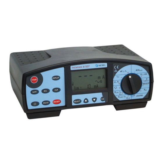
MI 2087 Instaltest 61557 Instrument description 2. Instrument description 2.1. Front panel Fig. 1. Front panel... - Page 9 MI 2087 Instaltest 61557 Instrument description Legend: ON/OFF key, to switch ON or OFF the instrument. Auto OFF will occur automatically 10 minutes after last strike to any key or function switch rotation. RS 232 key, to communicate with PC. LAMP key, to turn ON or OFF display backlight.
-
Page 10: Connector Panel
MI 2087 Instaltest 61557 Instrument description • Trip-out Time (Nominal differential current, Multiplier of Nominal differential current and RCD type). • Trip-out current (Nominal differential current). • AUTO RCD test (Nominal differential current and RCD type). • Voltage Logging (Period between sampling and Total number of samples). •... -
Page 11: Bottom Side
MI 2087 Instaltest 61557 Instrument description 2.3. Bottom side Fig. 3. Bottom side Legend: Nylon strip (it serves the operator to carry the instrument hung on his neck). Auxiliary nylon strip (it serves the operator to fix the instrument along his body). Plastic cover (it fixes nylon strip to the instrument). -
Page 12: Standard Accessories
MI 2087 Instaltest 61557 Instrument description 2.4. Standard accessories See attached sheet, to compare received set of accessories with listed one. 2.5. Optional accessories See attached sheet, to check the list of possible optional accessories, which may be supplied upon request. 2.6. -
Page 13: Accessories Required For Specific Measurement
MI 2087 Instaltest 61557 Instrument description 2.7. Accessories required for specific measurement The table below presents accessories (standard or optional) required for specific measurement. The accessories marked as optional may also be standard ones in some set configurations; Please see attached list of standard accessories for your set configuration or contact your dealer for further information. -
Page 14: Measurement Instructions
MI 2087 Instaltest 61557 Measurement instructions 3. Measurement instructions 3.1. Insulation resistance There are different objects, where insulation resistance is to be measured, in order to assure safety against electric shock. Let’s list a few examples: • Insulation resistance between installation conductors (all combinations). •... - Page 15 MI 2087 Instaltest 61557 Measurement instructions Step 2 • Set Nominal Test Voltage. How to set the Test Voltage? • Press the SELECT key twice and release it, to enter “Test voltage adjustment mode”, the following menu will be displayed: Last set Nominal test voltage is blinking.
- Page 16 MI 2087 Instaltest 61557 Measurement instructions Available low limit Step values (MΩ) (MΩ) 0,01 0,01 ÷ 0,25 0,05 0,25 ÷ 1 1 ÷ 10 10 ÷ 200 Last set Low limit value is blinking. Fig. 6. Low Limit Value adjustment menu and the Table of available limit values •...
- Page 17 MI 2087 Instaltest 61557 Measurement instructions Notes! • In case of present external voltage higher than 29 V a.c./d.c. between test terminals, the Insulation Resistance measurement will not be carried out after pressing START key, but the voltage will be displayed, equipped with “!” mark! Beep warning sound will be affected too.
-
Page 18: Varistor Over-Voltage Protection Devices
MI 2087 Instaltest 61557 Measurement instructions 3.2. Varistor Over-voltage Protection Devices For general information concerning the measurement, refer to enclosed handbook Measurements on electric installations in practice and theory. How to carry out the Breakdown voltage measurement? Step 1 • Connect Universal test cable to Instaltest 61557. - Page 19 MI 2087 Instaltest 61557 Measurement instructions • Use the ↑ ↑ ↑ ↑ and ↓ ↓ ↓ ↓ keys, to set required High Limit Value. Individual strike will increase/decrease the value for one step, while continuous pressure will increase/decrease it continuously. If test results are not to be compared with High Limit Value at all, then press the CLR key, no will be displayed instead of set value.
- Page 20 MI 2087 Instaltest 61557 Measurement instructions Step 5 • Press the START key and release it. Test voltage starts to rise (500 V/s) and as soon as varistor’s forward current reaches the value of 1 mA (Breakdown Voltage is defined at that current), the voltage will be displayed. Generator will stop to generate test voltage.
-
Page 21: Continuity Of Protective Conductors
MI 2087 Instaltest 61557 Measurement instructions 3.3. Continuity of protective conductors Continuity of protective conductors is to be measured, before mains voltage is connected to tested installation (new or adapted installations). Max. allowed resistance value depends on power of connected loads, used installation system (TN, TT) etc. - Page 22 MI 2087 Instaltest 61557 Measurement instructions Last set High Limit Value is blinking. Available high limit Step values (Ω) (Ω) 0,0 ÷ 20,0 Fig. 13. High Limit adjustment menu and the table of available high limit values • Use the ↑ ↑ ↑ ↑ and ↓ ↓ ↓ ↓ keys, to set required High Limit value. Individual strike will increase/decrease the value for one step, while continuous pressure will increase/decrease it continuously.
- Page 23 MI 2087 Instaltest 61557 Measurement instructions Step 4 • Connect test leads to tested object according to the figures below. MPEC..Main Potential Equilizing Collector PCC3 PCC.....Protection Conductor Collector L/L1 PCC1 PCC2 MPEC PE/L3 Option A 1012 N/L2 Fig. 15. Connection of Universal Test Cable and optional Probe Test Lead (Order No.
- Page 24 MI 2087 Instaltest 61557 Measurement instructions Notes! • In case of present external voltage higher than 9 V a.c./d.c. between test terminals, the Continuity measurement will not be carried out after pressing START key, but the voltage will be displayed, equipped with “!” mark! Beep warning sound will be affected too.
-
Page 25: Continuity
MI 2087 Instaltest 61557 Measurement instructions 3.4. Continuity The function is intended to be used especially when arranging terminal-to-terminal connections, maintaining and/or repairing electric equipment, carrying out auxiliary measurements etc. The function operates continuously and serves as ordinary Ω- meter with low test current. For additional general information concerning Continuity measurement, refer to enclosed handbook Measurements on electric installations in practice and theory. - Page 26 MI 2087 Instaltest 61557 Measurement instructions Fig. 18. Connection of Universal Test Cable Option A 1002 Fig. 19. Connection of optional Tip Commander (Order No. A 1002) • Press the START key again after finishing the measurement, last result will stay displayed.
-
Page 27: Rcd - Contact Voltage And Fault Loop Resistance
MI 2087 Instaltest 61557 Measurement instructions 3.5. RCD - Contact Voltage and Fault Loop Resistance For general information concerning Contact Voltage / Fault Loop Resistance measurement refer to enclosed handbook Measurements on electric installations in practice and theory. How to carry out the measurement? Step 1 •... - Page 28 MI 2087 Instaltest 61557 Measurement instructions Step 4 • Select Type of involved RCD as follows: • Press the SELECT key after setting Nominal differential current, last set type starts to blink. • Select appropriate type using the ↑ ↑ ↑ ↑ and ↓ ↓ ↓ ↓ keys. Standard (General) type (G is displayed) or Selective type (S is displayed) can be selected.
- Page 29 MI 2087 Instaltest 61557 Measurement instructions Fig. 22. Connection of Universal Test Cable Step 7 (Uc function is selected) • Press the START key and release it. Measurement will be carried out and result (Uc at I - standard RCD or Uc at 2I - selective RCD) will be displayed.
-
Page 30: Rcd - Trip-Out Time
MI 2087 Instaltest 61557 Measurement instructions 3.6. RCD - Trip-out Time In order to assure safe conditions, RCD device must trip-out within a certain time, in case of present fault on connected electric appliance. See allowed trip-out time ranges in the following table. Type of RCD Remark ∆... - Page 31 MI 2087 Instaltest 61557 Measurement instructions Step 3 • Select Multiplier of Nominal differential current as follows: • Press the SELECT key after setting Nominal differential current, last set Multiplier starts to blink. • Select appropriate value by using the ↑ ↑ ↑ ↑ and ↓ ↓ ↓ ↓ keys. The following values are available to be selected: ×1/2, ×1, ×2, ×5.
- Page 32 MI 2087 Instaltest 61557 Measurement instructions Test of Selective RCD For safety reason, Contact voltage measurement is carried out (regardless of RCD type) before Trip-out Time measurement is realised. As the Selective type of RCD (delayed trip-out) operates on basis of integration of fault current, it is necessary to relax it, before Trip-out Time measurement is carried out, otherwise the test is not relevant.
-
Page 33: Rcd - Trip-Out Current
MI 2087 Instaltest 61557 Measurement instructions 3.7. RCD – Trip-out Current For general information concerning Trip-out current measurement, refer to enclosed handbook Measurements on electric installations in practice and theory. How to carry out the measurement? Step 1 • Connect test cable (Plug commander or Universal test cable) to Instaltest 61557. •... - Page 34 MI 2087 Instaltest 61557 Measurement instructions Notes! • If RCD trips during Contact voltage measurement (some fault or leakage current is probably already flowing to ground), rcd mark will start to blink. • Nominal differential current, set in this function, will be offered in other RCD functions (Contact Voltage, Trip-out Time and Auto RCD test)! •...
-
Page 35: Rcd - Automatic Test
MI 2087 Instaltest 61557 Measurement instructions 3.8. RCD - Automatic Test Purpose of the function is to carry out complete test of RCD and measurement of belonging parameters (Contact Voltage, Fault loop resistance and Trip-out time at different fault currents) in one set of automatic tests, led by the instrument. If any false parameter is noticed during this automatic test, individual parameter test is to be used for further investigation. - Page 36 MI 2087 Instaltest 61557 Measurement instructions Step 4 • Connect test cable to tested object (mains outlet or other test terminals), according to the figure 21. (Plug commander) or figure 22. (Universal test cable). Step 5 Press the START key and release it. Measurement will start to run, partial results will be currently displayed as follows: The following presentation is valid for Standard RCD type;...
- Page 37 MI 2087 Instaltest 61557 Measurement instructions test Trip-out time measurement, using test current Itest = I n, at positive start polarity of ∆ test current (0°). The display message, presented on left side of the next figure, will appear for a while. Successfully ended third test (RCD trips within allowed time period) will be followed by rcd message, informing the operator to reswitch the RCD;...
- Page 38 MI 2087 Instaltest 61557 Measurement instructions Fig. 31. Fifth test is running (left figure) and rcd message, displayed after tripping out RCD (right figure) After reswitching RCD, sixth test will follow automatically. test Trip-out time measurement, using test current Itest = 5I n, at negative start polarity of ∆...
- Page 39 MI 2087 Instaltest 61557 Measurement instructions Test of Selective RCD For safety reason, Contact voltage measurement is carried out in each step (regardless of RCD type), before Trip-out Time measurement is done. As the Selective type of RCD (delayed trip-out) operates on basis of integration of fault current, it is necessary to relax it, before Trip-out Time measurement is carried out, otherwise the test is not relevant.
-
Page 40: Fault Loop Resistance And Prospective Short-Circuit Current
MI 2087 Instaltest 61557 Measurement instructions 3.9. Fault Loop Resistance and Prospective Short-circuit Current For general information concerning the measurement, refer to enclosed handbook Measurements on electric installations in practice and theory. How to carry out the measurement? Step 1 •... - Page 41 MI 2087 Instaltest 61557 Measurement instructions Option A 1001 Fig. 34. Connection of optional Plug Commander (Order No. 1001) Fig. 35. Connection of Universal Test Cable Step 3 • Press the START key and release it. Measurement will be carried out and result displayed afterwards.
- Page 42 MI 2087 Instaltest 61557 Measurement instructions • Store displayed results for documentation purpose; see instructions how to store it in chapter 4.1. Storing of test results. If RCD trips during Contact voltage measurement, rcd message will be displayed blinking way. Notes! •...
-
Page 43: Line Resistance Rl-N/Rl-L And Prospective Short-Circuit Current
MI 2087 Instaltest 61557 Measurement instructions 3.10. Line Resistance R and Prospective Short- circuit Current For general information concerning the measurement, refer to enclosed handbook Measurements on electric installations in practice and theory. How to carry out the measurement? Step 1 •... - Page 44 MI 2087 Instaltest 61557 Measurement instructions Step 3 • Press the START key and release it. Measurement will be carried out and result displayed afterwards. • Check calculated Prospective Short-circuit Current, pressing the DISPLAY key. The current is calculated as follows: Ipsc = Un⋅ ⋅ ⋅ ⋅ 1,06 / R L-N(L) Where: Un ....115 V (100 V ≤...
-
Page 45: Voltage Logging
MI 2087 Instaltest 61557 Measurement instructions 3.11. Voltage Logging Mains voltage unstability may be important reason for different malfunctions noticed at sensitive electrical equipment, machinery, appliances etc. The unstability may appear periodically during a certain period of time (starting-up or switching off powerful machinery, transformers, distribution systems etc.). - Page 46 MI 2087 Instaltest 61557 Measurement instructions • Clear all potentially stored results, preparing enough free locations for the Logging operation, regardless of total number of all measurements set in continuation. If stored results are still needed for documentation purpose (they should not be erased in that case) then transfer them to PC first and then erase.
- Page 47 MI 2087 Instaltest 61557 Measurement instructions Notes! • Nominal input voltage range is 0 V ÷ 440 V. • Results of the Logging function can be transferred to PC for further analysing, all stored values will be transferred not only the min, max and AVG value. •...
-
Page 48: Phase Rotation
MI 2087 Instaltest 61557 Measurement instructions 3.12. Phase rotation For general information concerning the test, refer to enclosed handbook Measurements on electric installations in practice and theory. How to carry out the measurement? Step 1 • Connect test cable (Three phase cable or Universal test cable) to Instaltest 61557. - Page 49 MI 2087 Instaltest 61557 Measurement instructions Step 3 • Press the START key and release it. Measurement starts to run (continuous measurement), result is currently displayed; see an example of the result on the figure below. Fig. 42. Phase rotation test result •...
-
Page 50: Illumination
MI 2087 Instaltest 61557 Measurement instructions 3.13. Illumination How to carry out the illumination measurement? Step 1 • Connect LUXmeter probe to Instaltest 61557. • Set function switch to SENSOR position, the following menu will be displayed. Fig. 43. Illumination measurement initial menu Step 2 •... - Page 51 MI 2087 Instaltest 61557 Measurement instructions Step 3 • Position LUXmeter probe parallel to the surface to be evaluated. Turn on the LUXmeter probe pressing ON/OFF key. Green lamp should light. Fig. 45. LUXmeter probe positioning Step 4 • Press the START key and release it. Instrument will start measuring illumination. Press the START key to stop the measurement.
-
Page 52: Tracing Of Electric Installation
MI 2087 Instaltest 61557 Measurement instructions 3.14. Tracing of electric installation There are two possible manners to trace installation by using the Instaltest 61557 namely: • Instaltest 61557 loads installation under mains voltage in a pulsed manner. In that case, hand-held indicator follows electro-magnetic field, generated around the loaded conductor. - Page 53 MI 2087 Instaltest 61557 Measurement instructions ested conductor shall be disconnected from load (motor), enabling the test signal to spread along phase conductor. Option A 1001 Option A 1005 Fig. 49. Connection of Universal Test Cable and optional Plug Commander (Order No.
-
Page 54: Memory And Other Operations
MI 2087 Instaltest 61557 Memory and other operations 4. Memory and other operations 4.1. Storing of test results In order memory manipulation to be as clear as possible and recognition of measurement location stored result belongs to be as understandable as possible, practical model of electric installation is used. - Page 55 MI 2087 Instaltest 61557 Memory and other operations Fig. 51. General electric installation...
- Page 56 MI 2087 Instaltest 61557 Memory and other operations All test results can be stored, except the following: Continuity (auxiliary function), Phase rotation (comparative test) and Voltage/Frequency. How to store displayed test result? FUSE code is offered (blinking). Set FUSE code (001 up to 999 can be set). FUSE CABINET code is offered (blinking).
-
Page 57: Recalling Of Stored Results
MI 2087 Instaltest 61557 Memory and other operations 4.2. Recalling of stored results Stored results can be displayed whenever needed for visual check. Main result, potential subresults and potential function parameters as well as function identification number can be recalled. How to recall stored results? FUSE location will be offered (blinking). - Page 58 MI 2087 Instaltest 61557 Memory and other operations Fig. 53. Organisation of memory locations...
-
Page 59: Erasing Of Stored Results
MI 2087 Instaltest 61557 Memory and other operations 4.3. Erasing of stored results Two modes of erasing stored results are available namely: • All stored results can be erased in one step • A certain stored result only can be erased How to erase all stored results in one step? Change function switch position in order to exit any potentially started operation (recalling, storing test result …), then press the CLR key,... -
Page 60: Reset Of The Instrument
MI 2087 Instaltest 61557 Memory and other operations 4.5. Reset of the instrument If any malfunction is noticed when dealing with the Instaltest 61557, it is advisable RESET of the instrument to be carried out. In that case all settable parameters will be set to their initial values;... -
Page 61: Maintenance
MI 2087 Instaltest 61557 Maintenance 5. Maintenance 5.1. Batteries - Disconnect test cable and switch off the instrument, before removing battery compartment cover! - Hazardous voltage under the battery compartment cover! Battery condition is currently displayed; see the battery condition mark in the left side of display. -
Page 62: Fuses
MI 2087 Instaltest 61557 Maintenance One set of full-capacity batteries can supply the instrument for approx. 50 hours at the ratio measurement / pause = 5s / 25s. Commander and Locator batteries: Red lamp ON means low battery condition. Unscrew two screws on backside of the device in order to remove battery cover. -
Page 63: Cleaning
5.5. Service Repairs under or out of warranty time: Please contact your distributor for further information. Distributor’s address: Producer’s address: METREL d.d. Ljubljanska 77 SI-1354 Horjul Tel.: +386 1 75 58 200 Fax.: +386 1 75 49 226 http://www.metrel.si E-mail: metrel@metrel.si... -
Page 64: Technical Specification
MI 2087 Instaltest 61557 Technical specification 6. Technical specification 6.1. Functions Insulation resistance Continuity Meas. range Riso (Un ≥ 250V) ...(0.008 ÷ 1000)MΩ Display range Resolution Accuracy ........R (Ω) (Ω) Display range Resolution Accuracy* 0.0 ÷ 199.9 ±(3% of r. + 3D) Riso (MΩ) (MΩ) 200 ÷... - Page 65 MI 2087 Instaltest 61557 Technical specification Calculation .......... R = Uc / I Display range Resolution Accuracy ∆N Measurement principle..without auxiliary probe , (Ω) (Ω) L-PE Test current ..........< 0.5 I ∆N 0.00 ÷ 19.99 0.01 ±(5% of r. + 5D) 20.0 ÷...
-
Page 66: General Characteristics
MI 2087 Instaltest 61557 Technical specification Frequency Overall accuracy match to DIN 5032 Class B standard Illumination (LUX meter type C) Display range Resolution Accuracy Display range Resolution Accuracy f (Hz) (Hz) E (Lux) (Lux) 45.0 ÷ 65.0 ±(0.1% of r. 0.01 0.1 ÷...
Need help?
Do you have a question about the Instaltest 61557 MI 2087 and is the answer not in the manual?
Questions and answers