Table of Contents
Advertisement
Quick Links
Advertisement
Table of Contents

Related Manuals for METREL MI 3102


Summary of Contents for METREL MI 3102
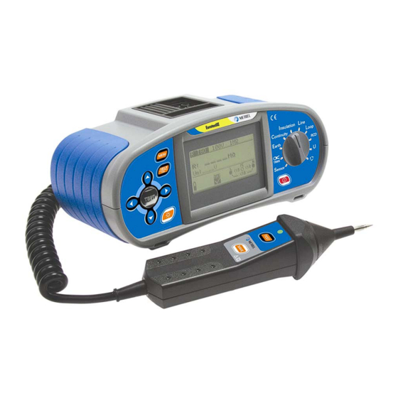
- Page 1 EurotestXE MI 3102 Short instructions Version 2.2 UK, Code No. 20 750 178...
- Page 2 Mark on your equipment certifies that this equipment meets the requirements of the EU (European Union) concerning safety and interference causing equipment regulations © 2004-2006 METREL No part of this publication may be reproduced or utilized in any form or by any means without permission in writing from METREL.
-
Page 3: Safety And Operational Considerations
Safety and operational considerations 1 Safety and operational considerations 1.1 Warnings • This document is a supplement to the Instruction manual! • Before using EurotestXE instrument read the Instruction manual carefully, otherwise use of the instrument may be dangerous for the operator, for the instrument or for equipment under test! •... -
Page 4: Battery Handling
Safety and operational considerations 1.2 Battery handling • When battery cells have to be replaced or before opening battery/fuse compartment cover, disconnect any measuring accessory connected to the instrument and power off the instrument, hazardous voltage inside! • Insert cells correctly, otherwise the instrument will not operate and the battery could be discharged. - Page 5 Measurements Illumination 3 Measurements 3.1 Illumination Set function Set parameters and limits Insulation Line Continuity Loop Earth Volt. Low limit illumination value [∗lux sets limit off, 0.1 lux ÷ 20.0 klux] Sensor Positioning diagram TEST Switch on the LUXmeter probe. Press the key.
- Page 6 Measurements TRMS current 3.2 TRMS current Set function Set parameters and limits Insulation Line Continuity Loop Earth Volt. High limit current value [∗mA sets limit off, 0.1mA ÷ 100.0 mA] Sensor Connection diagram Option A 1018 TEST Press the key. View results and press the MEM key to save them.
-
Page 7: Resistance To Earth
Measurements Resistance to earth 3.3 Resistance to earth Set function Set parameters and limits Insulation Line Continuity Loop Earth Volt. High limit resistance to earth value [∗Ω sets limit off, 1 Ω ÷ 1666 Ω] Sensor Connection diagram Test connector terminals are used as follows: L/L1 black test lead is used for the auxiliary earth electrode (H) N/L2 blue test lead is used for the earth electrode (E) PE/L3 green test lead is used for the probe (S) - Page 8 Measurements Continuity 3.4 Continuity Set function Set sub-function Set parameters and limits Insulation Line Continuity Loop Earth High limit resistance LowΩ [∗Ω sets limit off, 0.1 Ω ÷ Continuity Volt. 20.0 Ω] Sensor Connection diagram Continuity LowΩ MPEC..Main Potential Equilizing Collector PCC..Protection Conductor Collector PCC3 L/L1...
-
Page 9: Insulation Resistance
Measurements Insulation resistance 3.5 Insulation resistance Set function Set parameters and limits Insulation Line Continuity Loop Earth Nominal test voltage Volt. ÷ 1000 V [100 V Sensor Low limit resistance value [∗MΩ sets limit off, 0.01 MΩ ÷ 200 MΩ] Connection diagram switched off closed... - Page 10 Measurements Insulation monitoring in IT systems 3.6 Insulation monitoring in IT systems Set function Set sub-function Set parameters and limits Insulation Line Continuity Loop Earth First fault First fault current current high limit value Volt. IMD ckecking [∗F sets limit off, Sensor 3.0 mA ÷...
- Page 11 Measurements Line impedance and PSC 3.7 Line impedance (phase-neutral, phase-phase) Set function Set parameters and limits Insulation Line Continuity Loop Earth Fuse type [∗F sets limit off, BS88, BS3036, Volt. BS1361, BS1362, B, C, D] Fuse current rating [ 6 A ÷ 200 A] Sensor Fuse tripping time [ 0.4 s, 5 s] Connection diagram...
- Page 12 Measurements Fault loop impedance and PFC 3.8 Fault loop impedance Set function Set sub-function Set parameters and limits Insulation Line Continuity Loop Fuse type [∗F sets limit off, Earth Zs (rcd) BS88, BS3036, BS1361, BS1362, B, C, D] Volt. Fuse current rating Sensor [ 6 A ÷...
-
Page 13: Rcd Testing
Measurements RCD testing 3.9 RCD testing Set function Set sub-function Set parameters and limits Contact voltage Limit contact voltage Tripping time [25V, 50V] Tripping current Nominal differential RCD Insulation Line RCD autotest tripping current Continuity Loop [10 mA ÷ 1000 mA] Earth Multiplier of nominal Volt. -
Page 14: Voltage And Frequency
Measurements Voltage and frequency 3.10 Voltage and frequency Set function Insulation Line Continuity Loop Earth Volt. Sensor Connection diagram View results and press the MEM key to save them. Displayed results: Ul(1)-n(2): Voltage between phase and neutral conductors (or between phases L1 and L2) Ul(1)-pe(3): Voltage between phase and protective conductors (or between phases L1 and L3) Un(2)-pe(3): Voltage between neutral and protective conductors (or between phases L2 and L3) -
Page 15: Phase Sequence
Measurements Phase sequence 3.11 Phase sequence Set function Insulation Line Continuity Loop Earth Volt. Sensor Connection diagram option A 1110 result 1.2.3 result 2.1.3 View results and press the MEM key to save them. Displayed result: Ph: Phase sequence 1.2.3: Correct connection 2.3.1: Invalid connection -.-.-: Irregular voltages... -
Page 16: Maintenance
Maintenance 4 Maintenance 4.1 Replacing fuses • M 0.315 A / 250 V, 20×5 mm This fuse protects internal circuitry of low-value resistance function if test probes are connected to the mains supply voltage by mistake. • F2, F3 F 4 A / 500 V, 32×6.3 mm General input protection fuses of test terminals L/L1 and N/L2.
Need help?
Do you have a question about the MI 3102 and is the answer not in the manual?
Questions and answers