Table of Contents
Advertisement
Quick Links
Advertisement
Table of Contents

Related Manuals for Cole Parmer Stable Temp 282A


Summary of Contents for Cole Parmer Stable Temp 282A
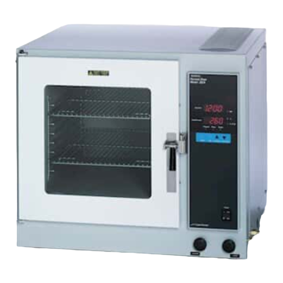
- Page 1 Stable Temp ® Model 282A Vacuum Oven 105714 • 7006281 Rev. 4...
- Page 2 Preface Models covered in this manual Catalog number Model number Voltage 05017-10 6281 115V 05017-15 6282 230V MANUAL NUMBER 105714 (7006281) ECNM-000078 8/02/18 Included correct vacuum in the temperature uniformity specification on page 2-1 28670 6/13/12 Update factory set heater runaway safety setting to 325°C, ±12° on pg 4-4 26741/SI-10360 11/9/10 Updated TCCB to comply with in-house test procedure QT049 (pg 6-13)
- Page 3 Preface CAUTION Contains Parts and Assemblies Susceptible to Damage by Electrostatic Discharge (ESD) Important Read this instruction manual. Failure to read, understand and follow the instructions in this manual may result in damage to the unit, injury to operating personnel, and poor equipment performance. Caution All internal adjustments and maintenance must be performed by qualified service personnel.
- Page 4 Preface Important operating and/or maintenance instructions. Read the accompanying text carefully. Potential electrical hazards. Only qualified persons should perform procedures associated with this symbol. Equipment being maintained or serviced must be turned off and locked off to prevent possible injury. Hot surface(s) present which may cause burns to unprotected skin, or to materials which may be damaged by elevated temperatures.
- Page 5 Preface Do You Need Information or Assistance on Cole-Parmer Equipment? The Cole-Parmer Instruments Sales Group can provide information on pricing and give you quotations. We can take your order and provide delivery information on major equipment items or make arrangements to have your local sales representative contact you. 1-800-323-4340 Cole-Parmer, Toll Free, US Cole-Parmer Instruments Product Service Support can supply technical information about...
-
Page 6: Table Of Contents
Table of Contents Section 1 Introduction ..........1-1 Section 2 Performance and Physical Data . -
Page 7: Introduction
Introduction Section 1 Before operation, always observe the following safety precautions: • This unit is not explosion proof. • Do not use in the presence of flammable or combustible materials; fire or explosion may result. Unit contains components that may ignite such materials. - Page 9 Performance and Physical Section 2 Data Temperature Temperature Range ..Ambient to 280°C, continuously adjustable with 1°C resolution Heat Rise Time Ambient to 100°C in <30 minutes, ....with temp set to 200°C Average Set-Point Accuracy .
-
Page 10: Performance And Physical Data
Section 2 Performance and Physical Data Recorder Outputs Temperature, Pins P3-1, P3-2 ..10 mv / °C Chamber Pressure, Pins P3-3, P3-4 100 mv / in Hg Connector Type: ....AMP 640456-4 Physical Characteristics External Dimensions . -
Page 11: Unpacking
Unpacking Section 3 Refer to the packing list below and be certain that all listed items are present. If any are missing, notify Cole-Parmer. Also, be certain to complete and return the included warranty card. Unpacking Checklist Description Oven Shelves (shipped in chamber) Hose Connectors Instruction Manual Warranty Card... -
Page 13: Control, Indicators And Connectors
Control, Indicators and Section 4 Connectors Before putting the Oven into operation, the user should become thoroughly familiar with the location and function of all controls, indicators, and connectors. Most are clearly labeled and located on or below the front panel, with the exception of the two (PURGE and VACUUM) hose connectors, which are located on the lower right side of the oven. - Page 14 Section 4 Controls, Indicators and Connectors LED Indicators AM: Indicates first 12-hour time is being displayed/programmed in the upper display window. Flashes when in Calibration mode. °C: Indicates chamber temperature (°C) is being displayed/programmed in the lower display window. in Hg: Indicates chamber absolute pressure is being displayed in the lower display window.
- Page 15 Section 4 Controls, Indicators, and Connectors Vacuum Inlet Port: A serrated hose fitting used to connect an auxiliary vacuum pump to the oven. Fitting accepts a 1/4-inch (inside diameter) hose. Purge Inlet Port: A serrated hose fitting used to connect an auxiliary gas source to the vacuum oven.
-
Page 16: Self-Diagnostic Safety Monitors
Section 4 Controls, Indicators and Connectors Self-Diagnostic A group of six messages alert the operator to heater and control malfunctions. The OTC (open thermocouple) and OVR (over temp) Safety Monitors errors alternately display in the TEMP/VACUUM display. The PWRF (power failure), BATT LOW (low battery) and CRC (calibration data corruption) are displayed in the DAY/TIME display window. -
Page 17: Installation And Assembly
Installation and Assembly Section 5 The oven is shipped assembled and ready for operation. However, before installing the oven, the operating site should be prepared to meet necessary requirements. Additionally, a few assembly procedures must be performed before the oven can be safely and properly operated. Site Requirements The standard plug configurations are shown in the illustration below. -
Page 18: Installation
Section 5 Installation and Assembly Site Requirements When using a tank atmosphere, a 1/4” tube to 1/4” pipe adapter is required for the regulator outlet of the tank. This adapter is not supplied. (continued) A Swagelok B-400-7-4 adapter, or equivalent, may be used. Also, 9/16”, and 1-1/8”... -
Page 19: Operation
Operation Section 6 Energize the oven by switching the ON/OFF toggle to the ON position. The upper display will show VER while the lower display will show 1.0, indicating the current software version. Next, the DAY/TIME display will begin alternating between the day of week and the time of day. At the same time, the TEMP/VACUUM display will alternate between chamber temperature (°C) and chamber pressure (in Hg). -
Page 20: Main Controller Menus
Section 6 Operation Main Controller Table 3: Adjust Temperature Offset (Menu 2) Menus Step Key Entry Action Display Press MENU until ADJT is dis- Use the UP/DOWN keys to adjust the ADJT 00 played, then press SET temperature offset. (Range ±30°C) Press SET or wait 2 seconds Unit returns to the default menu. -
Page 21: Establishing Operating Conditions
Section 6 Operation Main Controller Table 7: Program Edit Mode (Menu 6) Menus (continued) Step Key Entry Action Display Unit enters the program edit mode Press MENU until PSET is and points to MONday, step 1. Use MON1 displayed, then press SET the UP/DOWN keys to select the day and step. -
Page 22: Auxiliary Pump Contacts
Section 6 Operation Auxiliary Pump The following procedure describes the proper method used for operating a vacuum pump using the auxiliary contacts supplied on the control board Contacts (Tabs 3 and 4). Note Vacuum pump operation can be performed independently as well. Warning High voltages are present when the side panel is removed. -
Page 23: Setting The Temperature
Section 6 Operation Auxiliary Pump 6. Reattach the side panel using the six side panel screws. Contacts (continued) 7. Connect the vacuum hose to the Vacuum Inlet Port on the side of the oven and open the Vacuum valve. Close the door and the Purge Inlet Port by turning Purge valve clockwise completely. -
Page 24: Operation In A Static Environment
Section 6 Operation Operation in a Static Static environment is defined as operation at atmospheric pressure and with air - as it is present. In this case, the operator would simply place the Environment sample in the oven chamber and set the desired temperature. Operation in a Controlled Controlled environment is defined as operation with the samples in an inert gas. -
Page 25: Setting The Time And Day
Section 6 Operation Temperature/Pressure When the oven reaches a stable operating condition, the display temperature should indicate the actual center chamber temperature Offsets (±2.0°C). In the event a more accurate display reading is needed, the offset parameter, located in the MAIN MENU, can compensate for the error. To enter an offset value, press the MENU key until the upper display window shows ADJT (adjust temperature) then press UP/DOWN arrow keys to enter an offset for the display temperature. -
Page 26: Programming The Oven
Section 6 Operation Programming the Oven The oven controller is capable of handling 8 instructions per day, 7 days a week. Programming the controller is not difficult. Table 7, listed as MENU 6 - Program Edit Mode, provides step by step instructions for setting the control temperature and/or vacuum pump operation at any given time of day or day of the week. -
Page 27: Program Execution - Enabling/Disabling
Section 6 Operation Programming the Oven Tuesday: (continued) Repeat steps from Monday except Step 2. Have oven shut down after 100°C operation. Wednesday: Repeat Tuesday. Thursday: Repeat Monday. Friday: Repeat Monday. Using the information in MENU 6 (Table 7: Program Edit Mode), the program could be set up as shown in the Sample Program Array on the following page. -
Page 28: Calibration Procedure
Section 6 Operation SAMPLE PROGRAM ARRAY STEPS MONDAY TUESDAY WEDNESDAY THURSDAY FRIDAY SATURDAY SUNDAY Temp: 100°C Temp: 100°C Temp: 100°C Temp: 100°C Temp: 100°C Temp: OFF Temp: OFF Pump: ON Pump: ON Pump: ON Pump: ON Pump: ON Pump: ON Pump: ON Time: 8:00 AM Time: 8:00 AM Time: 8:00 AM... -
Page 29: Calibration Mode
Section 6 Operation Calibration Mode Follow the instructions below to access the calibration mode: 1. Set the POWER switch to the OFF position. 2. Remove the right side panel. Note Refer to instructions for removing the side panel in Auxiliary Pump Contacts before proceeding. - Page 30 Section 6 Operation Table 8: Calibration Menus Prompt Calibration Routine Comments Four options. Selectively clears data INIT Initialize data memory. variables, program and clock. Resets all calibration data to defaults. Requires two temperature points (T2 -T1) Measure and Control thermocouple TCCB >100°C temperature control loop is on calibration.
- Page 31 Section 6 Operation TCCB-Thermocouple Calibration Before beginning the temperature calibration, place a NIST calibrated thermometer in the center of the vacuum oven chamber and close the door. Press the MENU key until the upper display shows TCCB, then press the SET key. The unit enters the thermocouple calibration mode and displays the first temperature set-point (flashing).
- Page 32 Section 6 Operation VCMC-Vacuum Calibration (continued) Another method is to read the pressure directly from a temperature compensated barometer that can be adjusted for altitude. This method will give the pressure at the elevation of the calibration site without the need for any additional calculations or corrections.
- Page 33 Section 6 Operation VCMC-Vacuum Calibration (continued) 5. Press the SET key again to enter the value. The controller will sample the pressure and adjust the display to it. Note The controller will sample the vacuum data, then it will automatically close the auxiliary vacuum pump contacts for the second- point calibration.
- Page 34 Section 6 Operation Table 9. Pressure at Atmosphere; Source U.S. Standard Atmosphere, P.62 (NASA) Pressure Altitude (ft.) Inches of Hg Torr(mm of Hg) -1000 31.02 787.87 15.25 -500 30.47 773.83 14.94 Sea Level (0) 29.92 760.00 14.70 29.38 746.37 14.43 1000 28.86 732.93...
- Page 35 Section 6 Operation D/AC-Temperature/Vacuum Recorder Outputs Repeat the process until the voltmeter indicates +3.00VDC. Press the MENU key to accept the new calibration data and enter the vacuum pressure recorder calibration, indicated by D/AV in the upper display. To begin calibrating the vacuum pressure recorder output, move the voltmeter leads to output pins P3-3 (+) and P3-4 (-).
-
Page 37: Maintenance
Maintenance Section 7 The Model 282A is constructed and finished with materials that provide long maintenance-free service. All that is normally required is a routine cleaning of the exterior surfaces, oven shelf, and oven floor. Use a mild detergent for this purpose. Additionally, all external line connections for inert atmospheres should be checked for tightness on a weekly basis. -
Page 38: Door Alignment Procedure
Section 7 Maintenance Door Alignment A good seal around the door is critical, particularly when operating the oven with a vacuum environment. Therefore, the following procedure Procedure should be performed carefully. Refer to the illustrations below and perform the following. 1. - Page 39 Section 7 Maintenance Door Alignment 6. Draw a vacuum by pressing on both left and right sides of the door using your hands. Close vacuum valve at 25 inches of Hg. Procedure (cont.) 7. Tighten the two bolts for each hinge while lightly pressing each corner of the door in the area of the hinge being tightened.
-
Page 41: Service
Service Section 8 Caution Only trained personnel should perform service on this oven. Correcting a malfunction in the Oven primarily involves replacing the defective component. Components that can be replaced are listed under Table 11 in Replacement Parts. Most components can be accessed by removing the right side panel. - Page 42 Section 8 Service Table 10: Trouble Analysis Chart Symptom Probable Cause Corrective Action Oven does not heat. CRC error. Error found in calibration data. Recalibrate unit. Oven does not heat. OTC error. Open Control Thermocouple Check T.C. continuity; replace if open. Oven does not heat.
-
Page 43: Replacement Parts
Section 8 Service Replacement Parts Cole-Parmer Vacuum Oven... -
Page 44: Electrical Schematic
Section 9 Electrical Schematic 115V Schematic 230V Schematic Cole-Parmer Vacuum Oven... - Page 45 Cole-Parmer 625 East Bunker Court Vernon Hills, IL 60061-9872 1-800-323-4340 1-847-549-7600 www.coleparmer.com...
Need help?
Do you have a question about the Stable Temp 282A and is the answer not in the manual?
Questions and answers