
Related Manuals for Cole Parmer SPEX 3636 X-Press


Summary of Contents for Cole Parmer SPEX 3636 X-Press
- Page 1 XP-400 X-Press® Hydraulic Pellet Press for Spectroscopy Applications Operation Manual For 115V (04577-46) and 230V (04577-47) 1300-87043-1M, REV 3...
- Page 2 08840. SPEX SamplePrep is now part of Cole-Parmer®. The Cole-Parmer® XP-400 X-Press was formerly known as SPEX 3636 X-Press. Over the years, we’ve acquired many high-quality and reputable brands. After many years of continual growth, we realize our brands are all as brilliant as each other. Rather than have a portfolio of complementary brands, we felt consolidating them under one world- class brand name enabled us to offer a single and significant brand experience.
-
Page 3: Table Of Contents
XP-400 X-Press TABLE OF CONTENTS SECTION DESCRIPTION PAGE Introduction ........................4 Specifications ........................4 Unpacking ........................... 5 Press Layout ........................6 Setting Up .......................... 10 Display Screen and Controls ..................... 11 Operation .......................... 13 Performing a Test Run ...................... 13 Changing the Settings ....................... -
Page 4: Introduction
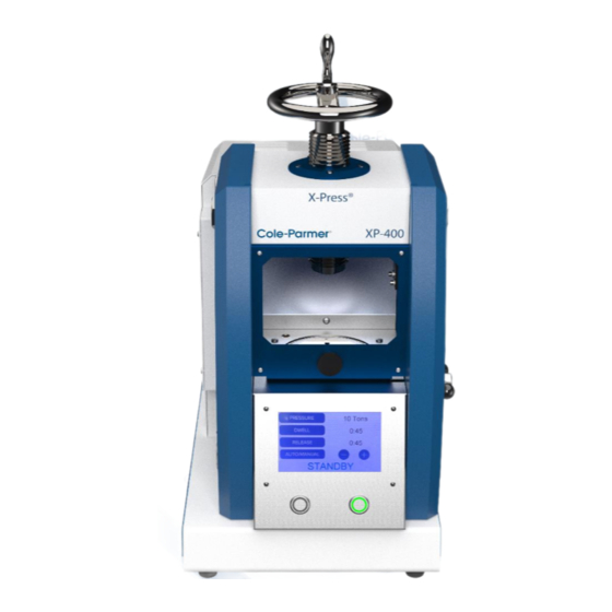
XP-400 X-Press 1.0 INTRODUCTION The XP-400 X-Press is an automated laboratory press intended for pressing sample pellets for spectroscopy. The press is programmable, so that repetitive pellet preparations may be carried out with a minimum of operator workload and a maximum of uniformity. The X-Press can also be operated manually. -
Page 5: Unpacking
XP-400 X-Press 3.0 UNPACKING At the factory, the X-Press is adjusted and tested for proper operation, and carefully packaged for shipping. Upon receipt, carefully inspect the exterior of the packing crate. If there is any visible damage, notify Cole-Parmer and file a claim with the carrier immediately. To unpack the X-Press, first remove the screws securing the crate lid;... -
Page 6: Press Layout
XP-400 X-Press 4.0 PRESS LAYOUT Figures 1 - 3 show the basic layout of the X-Press. The front view (Figure 1) shows the location of the touch screen and START and STOP buttons, which are used to operate the press. A loaded sample die is placed in the sample compartment on top of the platen and secured in place by the adjustment screw, using the hand-wheel. - Page 7 XP-400 X-Press HANDLE HANDWHEEL SAFETY DOOR ADJUSTMENT SCREW TEST BLOCK PLATEN/PISTON ACCESS PANEL DISPLAY SCREEN MANUAL PRESSURE RELIEF VALVE STOP START Figure 1 – Front View, XP-400 Automated X-Press 1300-87043-1M, REV 3 Cole-Parmer® Page 7 of 26...
- Page 8 XP-400 X-Press FILL PORT POWER SWITCH AC INPUT FUSE HOLDER Figure 2 - Rear View, XP-400 Automated X-Press (Side Access Panel Removed) 1300-87043-1M, REV 3 Cole-Parmer® Page 8 of 26...
- Page 9 XP-400 X-Press 1300-87043-1M, REV 3 Cole-Parmer® Page 9 of 26...
-
Page 10: Setting Up
XP-400 X-Press 5.0 SETTING UP Before operating the XP-400 X-Press, the unit must be properly set up and prepared. Follow these steps to ensure that the press is ready for use. The XP-400 X-Press is prefilled with oil at the factory prior to shipping. There is no need to drain oil and refill. 1. -
Page 11: Display Screen And Controls
XP-400 X-Press 6.0 DISPLAY SCREEN AND CONTROLS The touch screen on front of the XP-400 X-Press is used to program the press. Upon start- up, the Cole-Parmer and XP-400 X-Press logos will appear on the display screen, and the START and STOP buttons will flash. After a few seconds, INITIALIZING… will briefly be displayed at the bottom of the screen, indicating that initialization is in progress. -
Page 12: Operation
XP-400 X-Press 6.0 DISPLAY SCREEN AND CONTROLS (Cont’d) MANUAL is used when the operator prefers to run the press manually rather than automatically. When operating in manual mode, all other fields are inactive and cannot be adjusted. To switch from manual to automatic mode, touch the AUTO/MANUAL field. STANDBY will be displayed at the bottom of screen. -
Page 13: Performing A Test Run
XP-400 X-Press 7.1 Performing a Test Run The XP-400 X-Press can be tested using the default settings as soon as the setup procedure (Section 5.0) has been performed. The factory-programmed setting stored in memory will come up on the display screen: PRESSURE: 20 Tons DWELL:... -
Page 14: Changing The Settings
XP-400 X-Press 7.1 Performing a Test Run (Cont’d) 4. At the end of the dwell period, the main valve will open and the PRESSURE display will show the decreasing tonnage on the test block. The word RELEASE will be displayed at the bottom of the screen and the time remaining in the release field, counting down from 30 seconds. -
Page 15: Running An Automatic Cycle
XP-400 X-Press 7.3 Running an Automatic Cycle Before running a cycle, be sure that the pellet die is properly loaded, that the plunger is properly seated in the die, and that the die is centered on the platen. Turn the hand-wheel to bring the adjustment screw in contact with the top of the plunger, and tighten to take up any slack. -
Page 16: Manual Operation
XP-400 X-Press 7.3 Running an Automatic Cycle (Cont’d) Figure 5 – XP-400 X-Press® Automatic Cycle Profile 7.4 Manual Operation Although the XP-400 X-Press is easy to program for automatic operation, the press can be operated manually. To run manually: 1. Insert a loaded die into the press, center it on the platen, and turn the hand-wheel to bring the adjustment screw in contact with the top of the plunger. -
Page 17: Emergency Stops
XP-400 X-Press 7.4 Manual Operation (Cont’d) It is possible to increase the pressure during the dwell period. For instance, if after a specified dwell time, a second dwell time at a higher pressure is desired: 1. Press and hold the START button to activate the pump. 2. -
Page 18: Maintenance
XP-400 X-Press 8.0 MAINTENANCE 8.1 General Procedures The X-Press has been designed to provide trouble-free operation over a long period of time. To assure proper performance, perhaps the most important factor is cleanliness. Any spilled powders or hydraulic oil should be wiped up immediately. Although the X-Press is designed for industrial use, it should not be exposed to dust, moisture, etc., more than necessary, as those can affect both the mechanical and electronic functions. -
Page 19: Draining, Refilling, And Checking Hydraulic Oil
XP-400 X-Press 8.3 Draining, Refilling, and Checking Hydraulic Oil It is recommended that the oil be changed annually using 20W hydraulic oil, Cole-Parmer VPN 60361 (sold separately). To drain the hydraulic oil for an oil change, there is a drain plug on the bottom of the oil reservoir, reached through the base of the press. -
Page 20: Bleeding The Air
XP-400 X-Press 8.4 Bleeding the Air The X-Press hydraulic system should be bled of air (a) whenever hydraulic oil is added, and (b) after any repairs to the system. Follow these simple steps to complete this operation. 1. Set the press to manual mode by touching AUTO/MANUAL on the main screen. This field will change to display “MANUAL”. -
Page 21: Mechanical Operation
XP-400 X-Press 9.0 MECHANICAL OPERATION Figure 7 shows a simplified schematic of the mechanical layout of the XP-400 X-Press. Study this to become familiar with the basic operation of your X-Press. Figure 7 – Simplified Press Schematic The press has an oil reservoir maintained at atmospheric pressure, which is open to the air through the fill port. -
Page 22: Error Messages
XP-400 X-Press 9.0 MECHANICAL OPERATION (Cont’d) When the main valve opens, pressure is allowed to escape from under the piston, lowering the force (tonnage) on the pellet die. Both the main valve and the pump are microprocessor-controlled; the amount of force applied to the specimen in controlled by use of the touch screen on the front of the unit. -
Page 23: Troubleshooting
XP-400 X-Press 11.0 TROUBLESHOOTING PROBLEM POSSIBLE CAUSE POSSIBLE SOLUTION Unplugged. Check power cord connections. Power switch is Press switch to on position. Press does not off. activate. Fuse is blown. Unplug the unit; pull out fuse holders to check fuses. If blown, locate and correct the cause. Replace both fuses (3AG 8-amp slow-blow only). -
Page 24: Warranty
XP-400 X-Press 12.0 WARRANTY Cole-Parmer® guarantees its products against defects in materials or workmanship for three years from the date of original shipment. Repairs, replacements, or parts are guaranteed for 30 days or for the remaining original warranty period (whichever is greater) for the item that was repaired or replaced. -
Page 25: Instrumental Disposal
XP-400 X-Press 13.0 INSTRUMENT DISPOSAL In accordance to the EU Directive 2012/19/EU covering Waste Electrical and Electronic Equipment, all equipment with the disposal symbol must not be disposed of with general waste. (See Figure 8) Disposal Label is located on the back of unit. Figure 8 –... -
Page 26: Contact Us
XP-400 X-Press 14.0 CONTACT US Repair Service Phone: 1.732.623.0465 Cole-Parmer 65 Liberty St Metuchen, NJ 08840 Attn: Service and Repair Please include RA Number on the shipping label. Germany T: +1.800.323.4340 or T: +49 (0) 9377 92030 +1.800.323.4340 E: de.sales@antylia.com E: sales@antylia.com W: coleparmer.de W: coleparmer.com...
Need help?
Do you have a question about the SPEX 3636 X-Press and is the answer not in the manual?
Questions and answers