Table of Contents
Advertisement
Quick Links
Cover
CPX4 AC-PLC Evaluation Kit M02D2
RTK0EE0009D02001BJ
16
RENESAS
PLC Modem LSI R9A06G061
All information contained in these materials, including products and product specifications, represents
information on the product at the time of publication and is subject to change by Renesas Electronics
Corp. without notice. Please review the latest information published by Renesas Electronics Corp.
through various means, including the Renesas Electronics Corp. website (http://www.renesas.com).
www.renesas.com
User's Manual
Rev.1.00 July 01, 2021
Advertisement
Table of Contents

Related Manuals for Renesas CPX4 AC-PLC


Summary of Contents for Renesas CPX4 AC-PLC
- Page 1 All information contained in these materials, including products and product specifications, represents information on the product at the time of publication and is subject to change by Renesas Electronics Corp. without notice. Please review the latest information published by Renesas Electronics Corp.
- Page 2 Renesas Electronics disclaims any and all liability for any damages or losses incurred by you or any third parties arising from the use of any Renesas Electronics product that is inconsistent with any Renesas Electronics data sheet, user’s manual or other Renesas Electronics document.
- Page 3 Unit Products The following usage notes are applicable to all Micro processing unit and Microcontroller unit products from Renesas. For detailed usage notes on the products covered by this document, refer to the relevant sections of the document as well as any technical updates that have been issued for the products.
- Page 4 (2) In no event shall Renesas Electronics Corporation be liable for any consequence arising from the use of this product.
- Page 5 Renesas or to a third party. (3) This document and this product CPX4 AC-PLC Evaluation kit M02D2 (RTK0EE0009D02001BJ) are copyrighted, with all rights reserved by Renesas. This document may not be copied, duplicated or reproduced, in whole or part, without prior written consent from Renesas.
- Page 6 Precautions for Safety In this document, several icons are used to insure proper handling of this product and also to prevent injuries to you or other persons, or damage to your properties. This chapter describes the precautions which should be taken in order to use this product safely and properly.
- Page 7 ⚫ Do not touch the high voltage area during live operation for debugging, probing, or any other purpose. ⚫ Renesas Electronics bears no responsibility for any consequences that may result from the improper or hazardous use of this board.
- Page 8 Warning for Installation: ⚫ Do not set this product in water or areas of high humidity. Make sure that the product does not get wet. Spilling water or some other liquid into the product may cause unrepairable damage. Warning for Use Environment: ⚫...
- Page 9 After use the equipment cannot be disposed of as household waste, and the WEEE must be treated, recycled and disposed of in an environmentally sound manner. Renesas Electronics Europe GmbH can take back end of life equipment, register for...
- Page 10 Name: Renesas Electronics Europe GmbH Address: Arcadiastrasse 10, 40472 Dusseldorf, Germany ・ Trademark and Type name Trademark: Renesas Product name: CPX4 AC-PLC BOARD Model name: RTK0EE0009D04001BJ ** Environmental Compliance and Certifications: Waste Electrical and Electronic Equipment (WEEE) Directive 2012/19/EU UK Government guidance regulatory notices...
- Page 11 How to Use This Manual 1. Purpose and Target Readers This manual is designed to provide the user with an understanding of the hardware functions and electrical characteristics of the evaluation board. It is intended for users designing applications and systems based on the board.
- Page 12 List of Abbreviations and Acronyms Abbreviation Full Form Analog Front End Federal Communications Commission Ground Potential Media Access Control Layer Micro Controller Unit On Chip Debugger OFDM Orthogonal Frequency Division Multiplexing Power Line Communication Physical Layer Service Access Point Software firmware UART Universal Asynchronous Receiver/Transmitter...
-
Page 13: Table Of Contents
Table of Contents Product Overview ............................15 Board configuration ............................15 Circuit function block diagram ......................... 18 Description of each part of CPX4 AC-PLC evaluation kit ................19 Board Dimensions ............................20 To begin evaluating AC-PLC communications ....................21 1.5.1 Items required for AC-PLC communication Evaluation................ - Page 14 PMOD conversion board ..........................39...
-
Page 15: Product Overview
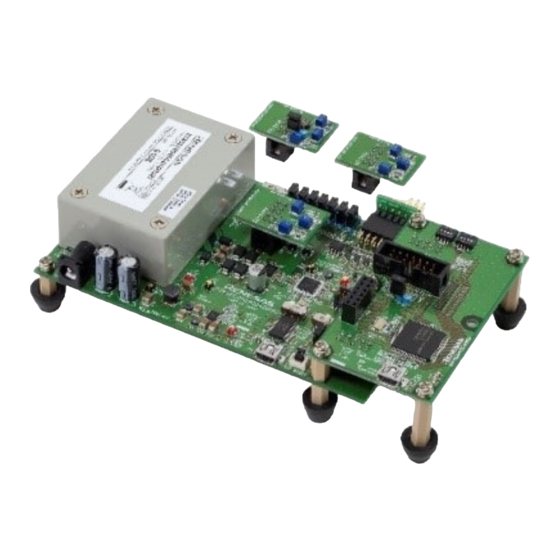
35k-90kHz, 150k-500kHz, and 35k-500kHz. PMOD conversion board: Pmod ™ connector female-male conversion board Figure 1-1 CPX4 AC-PLC Evaluation Kit Board Configuration The model name of the kit including the accessories is "RTK0EE0009D02001BJ" (display on the outer box). The individual model names for each board are shown in Table 1-1. - Page 16 CPX4 AC-PLC Evaluation Kit M02D2 RTK0EE0009D02001BJ 3.Interface Specifications Table 1-1 CPX4 AC-PLC Evaluation Kit supplied boards model names AC-PLC Board model name RTK0EE0009D04001BJ RX651 MCU Board model name RTK0EE0011C01001BJ Filter Board model name A2-type : RTK0EE0011Z01001BJ F2-type : RTK0EE0011Z02001BJ G2-type : RTK0EE0011Z03001BJ...
- Page 17 CPX4 AC-PLC Evaluation Kit M02D2 RTK0EE0009D02001BJ 3.Interface Specifications Table 1-2 List of specifications Product name CPX4 AC-PLC Evaluation Kit M02D2 RTK0EE0009D02001BJ Product Model Number RTK0EE0009D02001BJ PLC modem device CPX4 (R9A06G061) Control MCU RX651 (R5F5651EHDFP) AFE Devices ISL15102 (Intersil) : Power Amp (hereinafter, PA) + RX Step ATT : discrete 35kHz –...
-
Page 18: Circuit Function Block Diagram
CPX4 AC-PLC Evaluation Kit M02D2 RTK0EE0009D02001BJ 3.Interface Specifications Circuit function block diagram The circuit function block diagram of this product is shown in Figure 1-2, Figure 1-3, Figure 1-4, Figure 1-5. Figure 1-2 AC-PLC Board Block Diagram Figure 1-3 RX651 MCU Board Block Diagram Figure 1-4 Filter Board Block Diagram R30UZ0165EJ0100 Rev.1.00... -
Page 19: Description Of Each Part Of Cpx4 Ac-Plc Evaluation Kit
Description of each part of CPX4 AC-PLC evaluation kit Figure 1-6 shows a description of each part of the CPX4 AC-PLC evaluation kit. For a detailed explanation of the connectors, SWs and JPs of each board, refer to Chapter 3, Interface specifications and SW/JP switching. -
Page 20: Board Dimensions
CPX4 AC-PLC Evaluation Kit M02D2 RTK0EE0009D02001BJ 3.Interface Specifications Board Dimensions Each board in CPX4 AC-PLC evaluation kit is a four-layer construction (FR4). The dimensions of the boards are shown in Figure 1-7. Figure 1-7 Dimensions of CPX4 AC-PLC Evaluation Kit R30UZ0165EJ0100 Rev.1.00... -
Page 21: To Begin Evaluating Ac-Plc Communications
Obtain the latest version of the PHY-evaluation tool (CPX4 SimpleMAC GUI) and various manuals from the download site that that Renesas informed when the user registered as the PLC user. Information such as circuit diagrams and the latest version of the bill of materials can also be obtained if necessary. For the download site, refer to the "Precautions for Use"... -
Page 22: How To Use
CPX4 AC-PLC Evaluation Kit M02D2 RTK0EE0009D02001BJ 3.Interface Specifications HOW TO USE This chapter describes how to use AC-PLC board and Filter board. For descriptions of the connectors, SWs and JPs parts of each board, refer to Chapter 3 Interface specifications and SW/JP switching. - Page 23 CPX4 AC-PLC Evaluation Kit M02D2 RTK0EE0009D02001BJ 3.Interface Specifications Insertion loss at center frequency[kHz] frequency[kHz] -3dB -6dB Band Order frequency[dB] Low range High range Low range High range -3.1 44.7 428.1 35.1 541.9 Figure 2-3 G2-type Filter board for Global band TX-LPF is built into the PLC modem LSI.
-
Page 24: Example Of Setting Each Band
CPX4 AC-PLC Evaluation Kit M02D2 RTK0EE0009D02001BJ 3.Interface Specifications Example of setting each band After selecting the Filter board, change JP8 according to Table 2-1. For a detailed explanation of the connectors, SWs and JPs of each board, refer to Chapter 3 Interface specifications and SW/JP switching. -
Page 25: Methods For Evaluating Ac-Plc Communications Using Cpx4 Simplemac Gui
CPX4 AC-PLC Evaluation Kit M02D2 RTK0EE0009D02001BJ 3.Interface Specifications Method for evaluating AC-PLC communications using CPX4 SimpleMAC GUI The evaluation environment of AC-PLC communication using CPX4 SimpleMAC GUI is shown in Figure 2-5. For more information about board set and how to launch CPX4 SimpleMAC GUI, see the manual and the Quick Start Guide of CPX4 SimpleMAC GUI. -
Page 26: Interface Specifications And Sw/Jp Switching
CPX4 AC-PLC Evaluation Kit M02D2 RTK0EE0009D02001BJ 3.Interface Specifications Interface specifications and SW/JP switching This chapter describes the interface specifications and SW and JP switching of this product. AC-PLC Board This section explains the interface specifications and SWs/JPs settings of AC-PLC board. -
Page 27: Led (Led1, Led2, Led3, Led4)
CPX4 AC-PLC Evaluation Kit M02D2 RTK0EE0009D02001BJ 3.Interface Specifications Table 3-1 Usages of connectors, JPs, and SWs for AC-PLC board Connector, JP, SW name SW9, SW10 SWs for boot setting switching SW for UART-USB switching SW for MCU Enable/Disable switching Reset SW... -
Page 28: Jp (Jp21) For Switching External Reset Function Via Usb
CPX4 AC-PLC Evaluation Kit M02D2 RTK0EE0009D02001BJ 3.Interface Specifications which can reduce the transmit output by more than 10dB under low-load-impedance conditions. See Configuring Table 3-3. Table 3-3 JP(JP8) setting for inductor switching3 Inductor setting JP8 Setting Setting conditions Open Set when CENELEC-A band... -
Page 29: Plc-Connector ( Cn3)
CPX4 AC-PLC Evaluation Kit M02D2 RTK0EE0009D02001BJ 3.Interface Specifications 3.1.10 PLC-connector ( CN3) CN3 is a connector (AC inlet) for connecting to an AC line for communication. The AC-PLC board communicates via the PLC connector (CN3). Not used for power supply. -
Page 30: Mcu Board-Connection Connector (Cn6, Cn7)
CPX4 AC-PLC Evaluation Kit M02D2 RTK0EE0009D02001BJ 3.Interface Specifications 3.1.13 MCU board-connection connector (CN6, CN7) Table 3-7 and Table 3-8 show the connection with the RX651 MCU board. Table 3-7 CN6 connectors Terminal Terminal Function number name CPX_RESB Connected to the P0 terminal of CPX4... -
Page 31: Rx651 Mcu Board
CPX4 AC-PLC Evaluation Kit M02D2 RTK0EE0009D02001BJ 3.Interface Specifications RX651 MCU Board This section explains the interface specifications and SWs/JPs setting of RX651 MCU board. 3.2.1 Explanation of Connectors, SWs and JPs of RX651 MCU Boards Figure 3-2 shows the arrangement of the connectors, SWs and JPs, and Table 3-9 shows the usage. -
Page 32: Led (Led301, Led302)
CPX4 AC-PLC Evaluation Kit M02D2 RTK0EE0009D02001BJ 3.Interface Specifications 3.2.2 LED (LED301, LED302) LED301, LED302 are LEDs that can be used when developing applications for MCU (RX651). 3.2.3 MCU(RX651) General-purpose DIP-switch (SW301, SW302) These are the DIP SWs (SW301, SW302) with the terminal connections of the MCU (RX651) shown in Table 3-19. -
Page 33: Ocd-Connector (Cn305)
CPX4 AC-PLC Evaluation Kit M02D2 RTK0EE0009D02001BJ 3.Interface Specifications 3.2.6 OCD-connector (CN305) The OCD connector (CN305) is a connector for connecting an emulator. When connecting to a development tool via an emulator, set the target power supply to operate with "user power supply", and supply line power or external power to the AC-PLC board. -
Page 34: Usb Connector (Cn302)
CPX4 AC-PLC Evaluation Kit M02D2 RTK0EE0009D02001BJ 3.Interface Specifications 3.2.7 USB connector (CN302) The USB connector (CN302) can be used as a USB function. (Refer to the RX651 user manual for details.) Table 3-14 shows the USB connector connection. Table 3-14 CN302 connectors... -
Page 35: Connectors For Expansion Terminals (Cn300/Cn301)
CPX4 AC-PLC Evaluation Kit M02D2 RTK0EE0009D02001BJ 3.Interface Specifications 3.2.8 Connectors for expansion terminals (CN300/CN301) Table 3-16 and Table 3-17 show the expansion terminals connected to CN300 / CN301. Table 3-16 CN300 connectors Terminal Terminal name Function number PC0_MCU Connected to RX651-PC0... -
Page 36: Control Mcu(Rx651)
CPX4 AC-PLC Evaluation Kit M02D2 RTK0EE0009D02001BJ 3.Interface Specifications 3.2.9 Control MCU(RX651) RX651 MCU board is equipped with RX651 as MCU for control. Table 3-18 and Table 3-19 show the connection information of the control MCU terminals. For unused terminals of the MCU connected to CPX4, set them to the input port. Also, set other unused terminals to the input ports and enable the built-in pull-up function. - Page 37 CPX4 AC-PLC Evaluation Kit M02D2 RTK0EE0009D02001BJ 3.Interface Specifications Table 3-19 RX651MCU terminal connection 2/2 Terminal Terminal name Connection destination Remark (Recommended setting when not in use) number MCU(RX651) side CN304-5 Built-in pull-up when not in use CN300-1 Output HIGH when not in use...
-
Page 38: Filter Board
CPX4 AC-PLC Evaluation Kit M02D2 RTK0EE0009D02001BJ 3.Interface Specifications Filter Board This section describes the interface specifications and JP sets of the Filter board for RX-BPF. 3.3.1 Explanation of Connectors and JP of Filter Board Figure 3-4 is the placement of connectors and JP, and the applications are shown in Table 3-20. -
Page 39: Filter Setting For Low-Pass Noise Suppression Jp (Jp201)
CPX4 AC-PLC Evaluation Kit M02D2 RTK0EE0009D02001BJ 3.Interface Specifications 3.3.2 Filter setting for low-pass noise suppression JP (JP201) JP201 is for selecting whether or not to insert a low-pass noise suppressing filter (20kHz or less) on F2-type filter board. Set it to short if it is used, and open if it is unused. The factory default is open. - Page 40 Revision history CPX4 AC-PLC Evaluation Kit M02D2 RTK0EE0009D02001BJ User’s Manual Rev. Date Description Page Summary - 1.00 July 01, 2021 First edition Issued...
- Page 41 Colophon CPX4 AC-PLC Evaluation Kit M02D2 RTK0EE0009D02001BJ User’s Manual Publication Date: Rev.1.00 July 01, 2021 Published by: Renesas Electronics Corporation...
- Page 42 Back Cover CPX4 AC-PLC Evaluation Kit M02D2 RTK0EE0009D02001BJ R30UZ0165EJ0100...
- Page 43 Mouser Electronics Authorized Distributor Click to View Pricing, Inventory, Delivery & Lifecycle Information: Renesas Electronics RTK0EE0009D02001BJ...
Need help?
Do you have a question about the CPX4 AC-PLC and is the answer not in the manual?
Questions and answers