Table of Contents
Advertisement
Quick Links
One Technology Way • P.O. Box 9106 • Norwood, MA 02062-9106, U.S.A. • Tel: 781.329.4700 • Fax: 781.461.3113 • www.analog.com
Evaluation Board for the Integer-N PLL Frequency Synthesizer
FEATURES
Self-contained board for generating RF frequencies
Contains the ADF4108—an 8 GHz frequency synthesizer IC
Accompanying software allows complete control of
synthesizer functions from a PC
EVALUATION KIT CONTENTS
EV-ADF4108EB1Z
board
CD that includes
Self-installing software that allows users to control the
board and exercise all functions of the device
Electronic version of the
Electronic version of the
Electronic version of the
ADDITIONAL EQUIPMENT
PC running Windows XP or more recent version
Spectrum analyzer
Oscilloscope (optional)
Power supplies of 5.5 V and 15 V
PLEASE SEE THE LAST PAGE FOR AN IMPORTANT
WARNING AND LEGAL TERMS AND CONDITIONS.
ADF4108
data sheet
UG-160
user guide
UG-476
user guide
EVALUATION BOARD
Evaluation Board User Guide
DOCUMENTS NEEDED
ADF4108
data sheet
REQUIRED SOFTWARE
Analog Devices Int-N software (Version 7 or higher)
ADIsimPLL
GENERAL DESCRIPTION
The
EV-ADF4108EB1Z
evaluate the performance of the
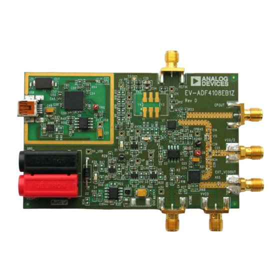
for phase-locked loops (PLLs). Figure 1 shows the board, which
contains the
reference input, the power supplies, a USB interface, and the RF
outputs. There is also an active loop filter and a VCO on board. The
user has the option of using an alternate loop filter and VCO by
connecting the board to the following SMA connectors: VTUNE
and CPOUT. The evaluation kit contains software that is com-
patible with Windows® XP and more recent versions to allow
easy programming of the synthesizer.
The USB interface allows software programming of the
device. A USB cable is included in the evaluation board kit to
allow software programmability.
Figure 1.
EV-ADF4108EB1Z
Rev. B | Page 1 of 16
evaluation board allows the user to
ADF4108
frequency synthesizer
ADF4108
synthesizer, an SMA connector for the
UG-160
ADF4108
Advertisement
Table of Contents

Related Manuals for Analog Devices UG-160


Summary of Contents for Analog Devices UG-160
-
Page 1: Features
Self-contained board for generating RF frequencies ADF4108 data sheet Contains the ADF4108—an 8 GHz frequency synthesizer IC REQUIRED SOFTWARE Accompanying software allows complete control of Analog Devices Int-N software (Version 7 or higher) synthesizer functions from a PC ADIsimPLL EVALUATION KIT CONTENTS GENERAL DESCRIPTION EV-ADF4108EB1Z... -
Page 2: Table Of Contents
UG-160 Evaluation Board User Guide TABLE OF CONTENTS Features ....................1 Power Supplies ................4 Evaluation Kit Contents ..............1 Input Signals...................4 Additional Equipment ..............1 Output Signals ................4 Documents Needed ................1 Default Operation .................4 Required Software ................1 Evaluation Board Software ...............5 General Description ................. -
Page 3: Quick Start Guide
QUICK START GUIDE Use the following steps to evaluate the ADF4108 device: Ensure that Analog Devices RFG.L Eval Board connected is displayed at the bottom left of the main window. Install the Int-N software (see the UG-476 user guide, PLL Connect the reference frequency to REFIN (SMA). -
Page 4: Evaluation Board Hardware
UG-160 Evaluation Board User Guide EVALUATION BOARD HARDWARE The evaluation board comes with a mini-USB cable to connect at the VCO/2 SMA connector. To use an alternate loop filter the evaluation board to the USB port of a PC. The evaluation and VCO, the charge pump output (CPOUT) and the VCO board silkscreen is shown in Figure 2. -
Page 5: Deleted Evaluation Board Setup Procedure And Figure 3 To Figure 6; Renumbered Sequentially
The control software for the EV-ADF4108EB1Z is provided on Confirm that Analog Devices RFG.L Eval Board connected is the CD included in the evaluation board kit. To install the displayed at the bottom left of the window (see Figure 3). If this... -
Page 6: Deleted Figure 7 To Figure 12
UG-160 Evaluation Board User Guide The Main Controls tab controls the PLL settings (see Figure 4). In the Registers tab, you can manually input the desired value to be written to the registers. Use the RF Settings section to control the output frequency. -
Page 7: Deleted Figure 13 To Figure 16
Select Device and Connection tab of the main window of the evaluation board software. Install the Analog Devices Int-N software (see the UG-476 10. In the Main Controls tab in the main window of the user guide, PLL Software Installation Guide). -
Page 8: Added Figure 15 And Figure 16
UG-160 Evaluation Board User Guide SIGNAL GENERATOR POWER SUPPLIES REFERENCE IN (REFERENCE OUT) TCXO CPOUT USB INTERFACE AGND ACTIVE LOOP LOCK +15V FILTER DETECT VCO/2 SPECTRUM ANALYZER EXTERNAL DC POWER POWER EXT_VCOOUT SUPPLIES EXTERNAL DC SUPPLY VTUNE VVCO Figure 6. Typical Evaluation Setup... -
Page 9: Changes To Figure 7
Evaluation Board User Guide UG-160 EVALUATION BOARD SCHEMATICS AND ARTWORK Figure 7. Evaluation Board Schematic (Page 1) Rev. B | Page 9 of 16... -
Page 10: Changes To Figure 8
UG-160 Evaluation Board User Guide Figure 8. Evaluation Board Schematic (Page 2) Rev. B | Page 10 of 16... -
Page 11: Changes To Figure 9
Evaluation Board User Guide UG-160 Figure 9. Evaluation Board Schematic (Page 3) Rev. B | Page 11 of 16... -
Page 12: Changes To Figure 10
UG-160 Evaluation Board User Guide Figure 10. Evaluation Board Schematic (Page 4) Rev. B | Page 12 of 16... -
Page 13: Changes To Figure 11 And Figure 12
Evaluation Board User Guide UG-160 Figure 11. Layer 1 (Component Side) Figure 12. Layer 2 (Ground Plane) Rev. B | Page 13 of 16... -
Page 14: Changes To Figure 13 And Figure 14
UG-160 Evaluation Board User Guide Figure 13. Layer 3 (Power/Ground Plane) Figure 14. Layer 4 (Solder Side) Rev. B | Page 14 of 16... -
Page 15: Changes To Table 1
Evaluation Board User Guide UG-160 BILL OF MATERIALS Table 1. Reference Designator Part Description +5V, +15V, 3V3_USB, 5V_USB, AVDD, Red test point CLK, DATA, DVDD, MUXOUT, OPBIAS, RIG, VP AGND, AGND1 Black test point Capacitor, 0603, 50 V, 680 pF, COG/NPO Capacitor, 0603, X7R, 50 V, 68 nF Capacitor, 0603, X7R, 50 V, 1.8 nF... -
Page 16: Related Links
By using the evaluation board discussed herein (together with any tools, components documentation or support materials, the “Evaluation Board”), you are agreeing to be bound by the terms and conditions set forth below (“Agreement”) unless you have purchased the Evaluation Board, in which case the Analog Devices Standard Terms and Conditions of Sale shall govern. Do not use the Evaluation Board until you have read and agreed to the Agreement. -
Page 17: Added Figure 26
Mouser Electronics Authorized Distributor Click to View Pricing, Inventory, Delivery & Lifecycle Information: Analog Devices Inc. EV-ADF4108EB2Z...
Need help?
Do you have a question about the UG-160 and is the answer not in the manual?
Questions and answers