Table of Contents
Advertisement
Quick Links
INSTALLATION MANUAL
AIR
CONDITIONER
Please read this installation manual completely before installing the product.
Installation work must be performed in accordance with the national wiring standards
by authorized personnel only.
Please retain this installation manual for future reference after reading it thoroughly.
Ceilling Concealed Duct
Original instruction
www.lg.com
MFL67939921
Rev.00_062818
Copyright © 2016 - 2018 LG Electronics Inc. All Rights Reserved.
Advertisement
Chapters
Table of Contents

Related Manuals for LG ABNW85GB9A0


Summary of Contents for LG ABNW85GB9A0
- Page 1 Installation work must be performed in accordance with the national wiring standards by authorized personnel only. Please retain this installation manual for future reference after reading it thoroughly. Ceilling Concealed Duct Original instruction www.lg.com MFL67939921 Rev.00_062818 Copyright © 2016 - 2018 LG Electronics Inc. All Rights Reserved.
-
Page 2: Table Of Contents
Table of Contents Table of Contents Safety Precautions Model Designation Product information Airborne Noise Emission Limiting concentration External Appearance Installation Places Selection of the best location The indoor unit installation Indoor Unit Drain Piping Drain test Heat Insulation Wiring Connection Remote Controller Installation Wired remote controller installation Wired Remote Controller... -
Page 3: Safety Precautions
Safety Precautions Safety Precautions To prevent the injury of the user or other people and property damage, the following instructions must be followed. n Be sure to read before installing the air conditioner. n Be sure to observe the cautions specified here as they include important items related to safety. n Incorrect operation due to ignoring instruction will cause harm or damage. - Page 4 Safety Precautions For installation, always con- Do not install the product Be sure the installation area tact the dealer or an Autho- on a defective installation does not deteriorate with rized Service Center. stand. age. • There is risk of fire, electric •...
- Page 5 Safety Precautions When the product is soaked Be cautious that water Ventilate the product from (flooded or submerged), could not enter the product. time to time when operating contact an Authorized Ser- it together with a stove, etc. vice Center. •...
- Page 6 Safety Precautions n Operation Do not expose the skin Do not use the product for Do not block the inlet or directly to cool air for long special purposes, such as outlet of air flow. periods of time. (Don't sit in preserving foods, works of the draft.) art, etc.
-
Page 7: Model Designation
Model Designation Model Designation Product information - Product Name : Air conditioner - Model Name : Serial number Function A : Basic, C/L : Plasma, E : Elevation grille Look L : Basic Chassis name only for Low Static Duct Chassis name Electrical rating G : 220~240/50,60/1... -
Page 8: Airborne Noise Emission
Model Designation Airborne Noise Emission The A-weighted sound pressure emitted by this product is below 70 dB. ** The noise level can vary depending on the site. The figures quoted are emission level and are not necessarily safe working levels. Whilst there is a correlation between the emission and exposure levels, this cannot be used reliably to determine whether or not further precautions are required. -
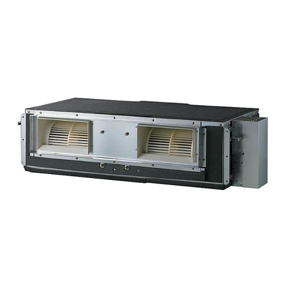
Page 9: External Appearance
External Appearance External Appearance • Ceiling Concealed Duct – Low static pressure L1/L2/L3 Chassis • Ceiling Concealed Duct – Mid static pressure M1/M2/M3 Chassis • Ceiling Concealed Duct – H-INV BR Chassis • Celling Concealed Duct – High static pressure B9 Chassis Installation Manual 9... -
Page 10: Installation Places
Installation Places Installation Places Selection of the best location Install the air conditioner in the location that satisfies the following conditions. • The place shall easily bear a load exceeding four times the indoor unit’s weight. • The place shall be able to inspect the unit as the figure. •... - Page 11 Installation Places Ceiling Concealed Duct – H-INV Ceiling Concealed Duct – High Static Inspection hole Top view Inspection hole (600X600) (600 x 600) Top view (unit: mm) Control box Control box (unit: mm) Front Front Front view Front view CAUTION : In case that the unit is installed near the sea, the installation parts may be corroded by salt, The installation parts (and the unit) should be taken appropriate anti-corrosion measures.
-
Page 12: The Indoor Unit Installation
The indoor unit installation The indoor unit installation Installation of Unit Install the unit above the ceiling correctly. CASE 1 POSITION OF SUSPENSION BOLT • Apply a joint-canvas between the unit and duct to absorb unnecessary vibration. • Apply a filter Accessory at air return hole. Ceiling Concealed Duct –... - Page 13 The indoor unit installation Ceiling Concealed Duct – Mid Static Drainage hole (Unit:mm) Indoor Unit Canvas Dimension Ceiling Duct Capacity (kBtu/h) Discharge Intake Flexible Duct 18 / 24 / 30 933.4 971.6 619.2 700 30 270 15.2 858 201.4 900 Duct 36 / 42 1 283.4 1 321.6 619.2 689.6 30...
- Page 14 The indoor unit installation Ceiling Concealed Duct – High Static (Unit:mm) Indoor Unit Canvas Ceiling Duct Dimension Discharge A B C D E F G H I J K L Intake Flexible Duct Capacity Duct (kBtu/h) 1 594 1 044 286 464 657 821 1 368 1 622 392 458 1 563 791 Air Discharge Ceiling Port...
- Page 15 The indoor unit installation • Select and mark the position for fixing bolts. • Drill the hole for set anchor on the face of ceiling. • Insert the set anchor and washer onto the suspension bolts for locking the suspen- Old building New building sion bolts on the ceiling.
- Page 16 The indoor unit installation CAUTION 1. Install declination of the indoor unit is very important for the drain of the duct type air conditioner. 2. Minimum thickness of the insulation for the connecting pipe shall be 10 mm. FRONT OF VIEW •...
- Page 17 The indoor unit installation CAUTION FOR GRADIENT OF Lay the drain hose with a downward inclination so water will drain out. UNIT AND DRAIN PIPING Thermal insulator • Always lay the drain with downward (Local supply) inclination. Drainage pipe Prevent any upward flow or reverse flow (Local supply) in any part.
-
Page 18: Indoor Unit Drain Piping
The indoor unit installation Indoor Unit Drain Piping • Drain piping must have down-slope : be sure not to provide up-and-down slope to prevent Upward Pipe clamp routing reversal flow. not allowed • During drain piping connection, be careful not Indoor unit to exert extra force on the drain port on the indoor unit. - Page 19 The indoor unit installation 1) Remove the Air Filter. 2) Check the drainage. • Spray one or two glasses of water upon the evaporator. • Ensure that water flows drain hose of indoor unit without any leakage. Installation Manual 19...
-
Page 20: Heat Insulation
The indoor unit installation Heat Insulation Be sure to give insulation work to refrigerant piping by covering liquid pipe and gas pipe separately with enough thickness heat-resistant polyethylene, so that no gap is observed in the joint between indoor unit and insulating material, and insulating materials themselves. When insulation work is insufficient, there is a possibility of condensation drip, etc. -
Page 21: Wiring Connection
The indoor unit installation Wiring Connection • Open the control box cover and connect the Remote controller cord and Indoor power wires. • Remove the control box cover for electrical connection between the indoor and outdoor unit. (Remove screws ①.) •... - Page 22 The indoor unit installation u Precautions when laying power wiring Use round pressure terminals for connections to the power terminal block. Power wire Round pressure terminal When none are available, follow the instructions below. • Do not connect wiring of different thicknesses to the power terminal block. (Slack in the power wiring may cause abnormal heat.) •...
-
Page 23: Remote Controller Installation
Remote Controller Installation Remote Controller Installation 1. Please fix tightly using provided screw after placing remote controller setup board on the place where you like to setup. - Please set it up not to bend because poor setup could take place if setup board bends. -
Page 24: Wired Remote Controller Installation
Remote Controller Installation 4. Please connect indoor unit and remote controller using connection cable. 12 V Please check if connector is normally connected. Signal Yellow Black Indoor Unit side Connecting cable 5. Please use extension cable if the distance between wired remote controller and indoor unit is more than 10 m. -
Page 25: Wired Remote Controller
Remote Controller Installation Wired Remote Controller PART DESCRIPTION Operation Display Windows Sub function Button Airflow Button Set/Cancel Button Function Setting Temperature Con- Button trol Button Ventilation Button On/Off Button Reservation Button Operation Mode Se- Up/Down/Left/Right lection Button Button Wireless Remote Room temperature Controller Receiver Button... -
Page 26: Optional Operation
Optional Operation Optional Operation Installer Setting -Test Run Mode A test run must be performed after installation. See the product manual for more details about test run. Press and hold button for more than 3 seconds to enter the installer settings mode. - If pressing only once briefly, it will enter the user settings mode. -
Page 27: Installer Setting - Setting Address Of Central Control
Optional Operation Installer Setting - Setting Address of Central Control This function is to be used when connecting to a central controller. See the central controller manual for more detailed functions. Press and hold button for more than 3 seconds to enter the installer settings mode. - If pressing only once briefly, it will enter the user settings mode. -
Page 28: Installer Setting -Thermistor
Optional Operation Installer Setting -Thermistor This function is to select a temperature sensor to determine the indoor temperature. Press and hold button for more than 3 seconds to enter the installer settings mode. - If pressing only once briefly, it will enter the user settings mode. Make sure to press and hold for more than 3 seconds. -
Page 29: Installer Setting-Remote Controller Master/Slave Setup
Optional Operation Installer Setting-Remote Controller Master/Slave Setup This function is the settings when controlling 2-remote controls or group control. Press and hold button for more than 3 seconds to enter the installer settings mode. - If pressing only once briefly, it will enter the user settings mode. Make sure to press and hold for more than 3 seconds. -
Page 30: Installer Setting-Dry Contact Mode Setting
Optional Operation Installer Setting-Dry Contact Mode Setting This function is available only for the products with dry contact device. Press and hold button for more than 3 seconds to enter the installer settings mode. - If pressing only once briefly, it will enter the user settings mode. Make sure to press and hold for more than 3 seconds. -
Page 31: Installer Setting-Celsius / Fahrenheit Switching
Optional Operation Installer Setting-Celsius / Fahrenheit Switching This function is used for switching the display between Celsius and Fahrenheit. (Optimized only for U.S.A) Press and hold button for more than 3 seconds to enter the installer settings mode. - If pressing only once briefly, it will enter the user settings mode. Make sure to press and hold for more than 3 seconds. -
Page 32: Installer Setting -Optional Function Setting
Optional Operation Installer Setting -Optional Function Setting This function is used when air Cleaner, heater, humidifier, elevation grill, ventilation KIT are installed additionally or the installed KIT is removed. Press and hold button for more than 3 seconds to enter the installer settings mode. - If pressing only once briefly, it will enter the user settings mode. -
Page 33: How To Set E.s.p
How to Set E.S.P? How to Set E.S.P? Installer Setting -E.S.P. This function is to facilitate the installation by assigning a fan speed value to each speed. • If the ESP is set improperly, it can cause an air conditioner malfunction. •... - Page 34 How to Set E.S.P? Set the ESP value using F G button. (The ESP value can be set from 1 up to 255, and 1 is the smallest value and 255 is the largest value.) Select a fan speed again using F G button, and set the ESP value for each speed. Ex) 120 set for Breeze (ESP value for Breeze : 120) Ex) 230 set for High...
-
Page 35: Installer Setting - Static Pressure Step Setting
How to Set E.S.P? Installer Setting - Static Pressure Step Setting This function is applied to only duct type. Setting this in other cases will cause malfunction. This function is only available on some models. This is the function that static pressure of the product is divided in 11 steps for setting. Press and hold button for more than 3 seconds to enter the installer settings mode. -
Page 36: Table 1
How to Set E.S.P? Ceiling Concealed Duct – Low static Table 1 Static Pressure [mmAq (Pa)] 0(0) 1(10) 2(20) 3(29) 4(39) 5(49) Model Step /min] Setting Value 32:01 32:02 32:03 32:04 32:05 32:06 ABNH09GL1A2 HIGH Static Pressure [mmAq (Pa)] 0(0) 1(10) 2(20) 3(29) -
Page 37: Low
How to Set E.S.P? Ceiling Concealed Duct – Mid static Table 2 Static Pressure[mmAq(Pa)] 2(20) 2.5(25) 3(29) 4(39) 6(59) 8(78) 10(98) 12(118) 13(127) 14(137) 15(147) Model Step Setting Value min] 32:01 32:02 32:03 32:04 32:05 32:06 32:07 32:08 32:09 32:10 32:11 ABNW18GM1A0 14.5 HIGH 16.5... -
Page 38: Abnw60Gm3A0
How to Set E.S.P? NOTE 1. Be sure to set the value refering table 2. Unexpected set value will cause mal-function. 2. Table 2 is based at 230 V. According to the fluctuation of voltage, air flow rate varies. 3. Factory Set(External Static Pressure) each Model. Model Factory set (E.S.P.) mmAq(Pa) ABNW18GM1A0... - Page 39 How to Set E.S.P? Ceiling Concealed Duct – H-INV Table 3 Static Pressure [mmAq (Pa)] 4(39) 5(49) 6(59) 8(78) 10(98) 12(118) Model Step /min] Setting Value 32:01 32:02 32:03 32:04 32:05 32:06 ABNW36GBRH0 HIGH Static Pressure [mmAq (Pa)] 4(39) 5(49) 6(59) 8(78) 10(98)
- Page 40 Step Setting Value min] 32:01 32:02 32:03 32:04 32:05 32:06 32:07 32:08 32:09 32:10 32:11 ABNW85GB9A0 HIGH NOTE 1. Be sure to set the value refering table 4. Unexpected set value will cause mal-function. 2. Table 4 is based at 230 V. According to the fluctuation of voltage, air flow rate varies.
-
Page 41: Self-Diagnosis Function
Self-diagnosis Function Self-diagnosis Function Indoor Unit Error Ex) Error 03 (Remote controller error) 3 Times 3 Times 3 Times LED02G (GREEN) 2 Seconds. 2 Seconds. LED 1 LED 2 Indoor Error Code Description (Red) (Green) status 1time ◑ Indoor Room sensor error 2times ◑...
Need help?
Do you have a question about the ABNW85GB9A0 and is the answer not in the manual?
Questions and answers