Table of Contents
Advertisement
INSTALLATION MANUAL
AIR
CONDITIONER
Please read this installation manual completely before installing the product.
Installation work must be performed in accordance with the national wiring
standards by authorized personnel only.
Please retain this installation manual for future reference after reading it
thoroughly.
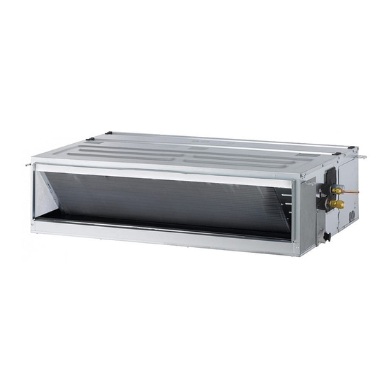
Ceiling Concealed Duct
MFL67939925
Rev.03_112720
Copyright © 2017 - 2020 LG Electronics Inc. All Rights Reserved.
www.lg.com
Advertisement
Table of Contents

Related Manuals for LG ABNW54LM3S1


Summary of Contents for LG ABNW54LM3S1
- Page 1 Installation work must be performed in accordance with the national wiring standards by authorized personnel only. Please retain this installation manual for future reference after reading it thoroughly. Ceiling Concealed Duct www.lg.com MFL67939925 Rev.03_112720 Copyright © 2017 - 2020 LG Electronics Inc. All Rights Reserved.
- Page 2 TIPS FOR SAVING ENERGY TIPS FOR SAVING ENERGY Here are some tips that will help you minimize the power consumption when you use the air conditioner. You can use your air conditioner more efficiently by referring to the instructions below: •...
- Page 3 SAFETY INSTRUCTIONS SAFETY INSTRUCTIONS The following safety guidelines are intended to prevent unforeseen risks or damage from unsafe or incorrect operation of the appliance. The guidelines are separated into ‘WARNING’ and ‘CAUTION’ as described below. This symbol is displayed to indicate matters and operations that can cause risk. Read the part with this symbol carefully and follow the instructions in order to avoid risk.
-
Page 4: Safety Instructions
SAFETY INSTRUCTIONS • Securely attach the electrical part cover to the indoor unit and the service panel to the outdoor unit. - If the electrical part cover of the indoor unit and the service panel of the outdoor unit are not attached securely, it could result in a fire or electric shock due to dust, water, etc. - Page 5 SAFETY INSTRUCTIONS Operation • Turn off the unit if strange sounds, smell, or smoke comes from it. - Otherwise, it may cause electrical shock or a fire. • Keep the flames away. - Otherwise, it may cause a fire. • Do not touch the power cable with wet hands when it taking out . - Otherwise, it may cause a fire or electrical shock.
- Page 6 SAFETY INSTRUCTIONS CAUTION Installation • Install the drain hose to ensure that drain can be securely done. - Otherwise, it may cause water leakage. • Install the product so that the noise or hot wind from the outdoor unit may not cause any damage to the neighbors.
-
Page 7: Table Of Contents
TABLE OF CONTENTS TABLE OF CONTENTS TIPS FOR SAVING ENERGY SAFETY INSTRUCTIONS INTRODUCTION Features INSTALLATION OF INDOOR Selection of the best location Installation of Unit Indoor Unit Drain Piping Drain test Piping insulation Wiring Connection INSTALLATION INSTRUCTION Remote controller installation Group control Installer Setting - How to enter installer setting mode Installer Setting - Test Run Mode... -
Page 8: Introduction
INTRODUCTION INTRODUCTION Features Air inlet vents Air outlet vents Remote Controller... -
Page 9: Installation Of Indoor
INSTALLATION OF INDOOR INSTALLATION OF INDOOR Selection of the best location Installation of Unit - The place shall easily bear a load exceeding Install the unit above the ceiling correctly. four times the indoor unit’s weight. - The place shall be able to inspect the unit as CASE 1 the figure. - Page 10 INSTALLATION OF INDOOR - Select and mark the position for fixing bolts. CASE 2 - Drill the hole for set anchor on the face of - Install the unit leaning to a drainage hole side ceiling. as a figure for easy water drainage. Position of console Bolt - A place where the unit will be leveled and that can support the weight of the unit.
- Page 11 INSTALLATION OF INDOOR CAUTION • Install declination of the indoor unit is very important for the drain of the duct type air conditioner. • Minimum thickness of the insulation for the connecting pipe shall be 19 mm. Front of view •...
-
Page 12: Indoor Unit Drain Piping
INSTALLATION OF INDOOR Indoor Unit Drain Piping Remove the air filter. - Drain piping must have down-slope (1/50 to 1/100): be sure not to provide up-and-down slope to prevent reversal flow. - During drain piping connection, be careful not to exert extra force on the drain port on Air filters the indoor unit. -
Page 13: Wiring Connection
INSTALLATION OF INDOOR Insulation material standard (mm) - residential Insulation material standard Insulation material (mm) standard (mm) If installed in an air-conditioned If installed in a non-air- (besides normal conditions for (unfavorable place (CASE 1) conditioned place (CASE 2) applies to residential use) conditions) (ex: bedroom, living room, etc.) - Page 14 INSTALLATION OF INDOOR CAUTION CAUTION • The connecting cable connected to the Precautions when laying power wiring indoor and outdoor unit should be complied with the following Use round pressure terminals for specifications (Rubber insulation, type connections to the power terminal block. H05RN-F approved by HAR or SAA).
-
Page 15: Installation Instruction
INSTALLATION INSTRUCTION INSTALLATION INSTRUCTION Please install the wired controller The connection cables of the wired mounting plate to the position you want controller can be set from two directions: with the screws provided. - Installation direction: slotted on the wall - Do not bend the mounting plate during surface, underside. - Page 16 12 V Black CAUTION Remove remote controller by inserting a screwdriver into the lower separating holes • Specification of LG supplied extension and twisting to release the controller from cable: AWG#22, 3 core shielded. backplate. (Model : PZCWRC1) - There are two separating holes. Please * Apply enclosed noncombustible individually separate one at a time.
-
Page 17: Remote Controller Installation
INSTALLATION INSTRUCTION Remote controller installation Since the room temperature sensor is in the remote controller, the remote controller box should be installed in a place away from direct sunlight, high humidity and direct supply of cold air to maintain proper space temperature. Install the remote controller about 5 ft(1.5 m) above the floor in an area with good air circulation at an average temperature. -
Page 18: Group Control
INSTALLATION INSTRUCTION Group control * When installing 2 remote controllers to one indoor unit with event When installing more than 2 units of air communication function, set the conditioner to one wired remote controller, master/slave of the remote controller. please connect as Figure.1. (Refer to remote controller master/slave selection) - If it is not event communication indoor... -
Page 19: Installer Setting - How To Enter Installer Setting Mode
INSTALLATION INSTRUCTION Installer Setting - How to enter installer setting mode CAUTION Installer setting mode is to set the detail function of the remote controller. If the installer setting mode is not set correctly, it can cause problems to the product, user injury or property damage. -
Page 20: Installer Setting - Test Run Mode
INSTALLATION INSTRUCTION Installer Setting - Test Run Mode After installing the product, you must run a Test Run mode. For details related to this operation, refer to the product manual. When pressing the button and button simultaneously for more than 3 seconds, the system will be entered into the installer setting mode. -
Page 21: Installer Setting - Setting Address Of Central Control
INSTALLATION INSTRUCTION Installer Setting - Setting Address of Central Control It's the function to use for connecting central control. Please refer to central controller manual for the details When pressing the button and button simultaneously for more than 3 seconds, the system will be entered into the installer setting mode. -
Page 22: Installer Setting - E.s.p
INSTALLATION INSTRUCTION Installer Setting - E.S.P. This is the function that decides the strength of the wind for each wind level and because this function is to make the installation easier. - If you set ESP incorrectly, the air conditioner may malfunction. - This setting must be carried out by a certificated-technician. -
Page 23: Installer Setting - Thermistor
INSTALLATION INSTRUCTION Installer Setting - Thermistor This is the function to select the temperature sensor to judge the room temperature. When pressing the button and button simultaneously for more than 3 seconds, the system will be entered into the installer setting mode. - After entering into the installer setting mode, select the thermistor sensor setting code value by pressing the... -
Page 24: Installer Setting - Remote Controller Master/Slave Setup
INSTALLATION INSTRUCTION Installer Setting - Remote Controller Master/Slave Setup It is a function for settings in group control, or 2-remote controller control. When pressing the button and button simultaneously for more than 3 seconds, the system will be entered into the installer setting mode. -
Page 25: Installer Setting - Celsius / Fahrenheit Switching
INSTALLATION INSTRUCTION Installer Setting - Celsius / Fahrenheit Switching This function is used for switching the display between Celsius and Fahrenheit. (Optimized only for U.S.A) When pressing the button and button simultaneously for more than 3 seconds, the system will be entered into the installer setting mode. -
Page 26: Installer Setting - Static Pressure Step Setting
INSTALLATION INSTRUCTION Installer Setting - Static Pressure Step Setting This function is applied to only duct type. Setting this in other cases will cause malfunction. This function is only available on some products. This is the function that static pressure of the product is divided in 11 steps for setting. When pressing the button and button simultaneously for more than 3... - Page 27 INSTALLATION INSTRUCTION [Table. 1] Static Pressure[mmAq(Pa)] Capacity 2(20) 2.5(25) 3(29) 4(39) 6(59) 8(78) 10(98) 12(118) 13(127) 14(137) 15(147) Step CMM Setting Value (kBtu/h) 32:01 32:02 32:03 32:04 32:05 32:06 32:07 32:08 32:09 32:10 32:11 14.5 HIGH 16.5 Static Pressure[mmAq(Pa)] Capacity 2(20) 2.5(25) 3(29) 4(39) 6(59)
- Page 28 INSTALLATION INSTRUCTION NOTE 1. Be sure to set the value refering table 1. Unexpected set value will cause mal-function. 2. Table 1 is based at 230 V. According to the fluctuation of voltage, air flow rate varies. 3. Factory Set(External Static Pressure) each Model Factory set (E.S.P.) Capacity (kBtu/h) mmAq(Pa)
-
Page 29: Dip Switch Setting
DIP SWITCH SETTING DIP SWITCH SETTING Indoor PCB Indoor PCB Indoor PCB Function Description Setting Off Setting On Default Selection of Master or Group Control Master Slave Slave Wired/Wireless remote Dry Contact Selection of Dry Contact controller Indoor PCB Auto Mode Mode Selection of Manual or...
Need help?
Do you have a question about the ABNW54LM3S1 and is the answer not in the manual?
Questions and answers