
Related Manuals for Badger Meter Oval Gear EPM2-STD


Summary of Contents for Badger Meter Oval Gear EPM2-STD
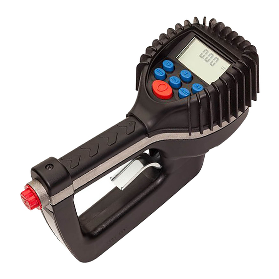
- Page 1 Electronic Preset Meter Model EPM2-STD, Standard Series User Manual AUT-UM-00933-EN-07 (April 2021)
-
Page 2: Table Of Contents
Electronic Preset Meter, Model EPM2-STD, Standard Series CONTENTS Scope of this Manual Safety Warning Symbol Explanation Warnings Meter Buttons LCD Display Meter Installation Relieve System Pressure Grounding Flushing Procedure Attach Meter to Hose Attach Nozzle to Meter Meter Operation Manual Mode Auto Batch Mode Operating Mode Functions Accumulated Total and Resettable total... -
Page 3: Scope Of This Manual
Scope of this Manual SCOPE OF THIS MANUAL This manual describes how to install, calibrate and operate an Electronic Preset Meter Read this manual before attempting any installation of the meter Keep this manual available for future use SAFETY Warning Symbol Explanation Indicates a hazardous situation, which, if not avoided, will result in death or serious personal injury WARNING Indicates a hazardous situation, which, if not avoided, could result in death or serious personal injury... -
Page 4: Meter Buttons
Meter Buttons METER BUTTONS Used to enter the batch quantity to be dispensed Used to display the accumulated total of fluid dispensed as well as the resettable total during Auto Batch and Manual mode Used to enter and exit the Manual or Auto Batch mode •... -
Page 5: Grounding
Meter Installation Grounding WARNING THE DISPENSING SYSTEM MUST BE GROUNDED TO PREVENT STATIC SPARKS AND RESULTING EXPLOSIONS. Movement of fluids through the dispensing system can create static electricity which can cause static sparks Static sparks can ignite volatile fumes, causing an explosion and fire Grounding reduces the risk of static sparking Ground all system components according to local, state and federal codes Pump: follow manufacturer's recommendations •... -
Page 6: Attach Nozzle To Meter
Meter Operation 3 Tighten completely with an open-ended, adjustable wrench (Figure Figure 5: Use wrench to tighten Attach Nozzle to Meter 1 Apply Loctite 243 sealant, or equivalent, to the end of the nozzle 2 Thread the nozzle onto the opposite end of the meter where the hose is installed (Figure Figure 6: Thread nozzle onto meter 3 Screw the nozzle in tightly with an open-ended, adjustable wrench... -
Page 7: Auto Batch Mode
Operating Mode Functions Auto Batch Mode Auto Batch mode allows you to program a batch size, then dispense it with a pull of the trigger When in Auto Batch mode, the AUTO icon displays in the lower left of the LCD screen and the batch quantity displays in the lower right 1 Press AUTO to enter Auto Batch from Manual mode 2 Change the batch size by pressing 10, 1, and 0.1 ◊... -
Page 8: Service
Service SERVICE Low Battery When the batteries need to be changed, a progression of warnings appears on the meter screen First, the Low Battery icon appears on the display, indicating the batteries are getting low and should be changed When the icon begins to flash, battery power is too low and meter functions are disabled Figure 11: Low battery icon Changing the Batteries... -
Page 9: Calculate Scale Factor
Change Factory Settings Change Unit of Measure Scale Factor Digits OTE: When Programming mode is entered, the current unit of measure flashes Unit of Measure 1 Press TOTAL to cycle through the four options; PT, QT, GAL, L 2 When the correct unit of measure is displayed, press RESET to select it The unit of measure stops flashing and the first number of the Scale Factor starts flashing OTE: If L (liters) is selected, the decimal point begins to flash Press TOTAL to toggle... -
Page 10: Dimensions
Dimensions Absolute Scale Factor For absolute scale factor, perform this test: 1 Run a batch through the meter 2 If the meter measures a different amount than the batch amount, the scale factor needs to be adjusted For example, if you run a 4 20 quarts batch and the display shows only 4 00 quarts, the scale factor needs adjustment 3 Divide the amount of liquid in the batch (4 20) by what the display shows (4 00) The result is the error factor (1 05) 4 Find the current scale factor by pressing and holding TOTAL and then AUTO For this example the current scale factor is... -
Page 11: Specifications
Specifications SPECIFICATIONS Flow Range* 0 25…10 gpm (1…38 lpm) Operating Pressure Range 5…1000 psi (0 35…69 bar) Operating Temperature Range 20…120° F (–7…49° C) Accuracy ± 0 5% 5-digit LCD Display Quarts, Pints, Gallons, Liters Inlet and Outlet Connections 1/2 in NPT (1/2 in BSPP) * Minimum and maximum flow range will vary with fluid viscosity PARTS Back of Meter... -
Page 12: Troubleshooting
Trademarks appearing in this document are the property of their respective entities Due to continuous research, product improvements and enhancements, Badger Meter reserves the right to change product or system specifications without notice, except to the extent an outstanding contractual obligation exists © 2021 Badger Meter, Inc All rights reserved...
Need help?
Do you have a question about the Oval Gear EPM2-STD and is the answer not in the manual?
Questions and answers