Table of Contents
Advertisement
Quick Links
Advertisement
Table of Contents

Subscribe to Our Youtube Channel
Related Manuals for IFM efector160 LR2750


Summary of Contents for IFM efector160 LR2750
- Page 1 Operating instructions Electronic level sensor LR2750...
-
Page 2: Table Of Contents
Contents 1 Preliminary note ....................4 1.1 Symbols used ....................4 2 Safety instructions ....................4 3 Items supplied......................5 4 Getting started .....................5 5 Functions and features ..................6 5.1 Applications ....................6 6 Function .......................7 6.1 Measuring principle ..................7 6.2 Other features of the unit ................7 6.2.1 Display functions ..................8 6.2.2 Analogue function ................8 6.2.3 Switching functions ................10... - Page 3 10.2 Explanation of the menu ................27 10.2.1 Main menu ..................27 10.2.2 EF level (extended functions) ............27 10.2.3 CFG level (configuration) ..............28 10.2.4 ENV level (environment) ..............28 10.2.5 SIM level (simulation) ...............28 11 Parameter setting .....................29 11.1 Parameter setting in general ..............29 11.2 First set-up (unit with factory setting) ............31 11.2.1 Entering the probe length ..............31 11.2.2 Carry out tank adjustment ..............32...
-
Page 4: Preliminary Note
12.4 Fault indications ..................38 12.5 Output response in different operating states ..........39 13 Technical data ....................39 14 Maintenance / Transport ..................40 14.1 Transport ....................40 15 Factory setting ....................41 1 Preliminary note 1.1 Symbols used ► Instructions > Reaction, result […] Designation of keys, buttons or indications →... -
Page 5: Items Supplied
• Mounting adapter / welding adapter (a launching plate if required → 5) Available accessories: www.ifm.com → Data sheet search → Accessories Only use accessories from ifm electronic gmbh. The optimum function is not ensured when using components from other manufacturers. -
Page 6: Functions And Features
5 Functions and features The unit continuously detects the level of liquids and viscous media in tanks and generates output signals according to the parameter settings. 2 outputs are available. They can be set separately. OUT1 Switching signal for level limit value / IO-Link OUT2 •... -
Page 7: Function
6 Function 6.1 Measuring principle fig. 5-1 fig. 5-2 The unit operates to the principle of guided wave radar. It measures the level using electromagnetic pulses in the nanosecond range. The pulses are transmitted by the sensor head and guided along the rod (fig. 5-1). -
Page 8: Display Functions
(→ 11.2.2)) • Display of the level and the switching status via display / LEDs • IO-Link function (→ 6.2.6) Technical data sheet at www.ifm.com → New search → Enter the article number 6.2.1 Display functions The unit displays the current level, either in mm, inch or in percent of the final value of the measuring range. - Page 9 I [mA] Curve of the analogue signal (measuring range scaled): I [mA] ASP2 AEP2 ① L: Level [ou2] = I (factory setting) ② A: Active zone = L-(I1+I2) [ou2] = [InEG] I1: Inactive zone 1 ASP2 Analogue start point I2: Inactive zone 2 (→ Technical data sheet) AEP2: Analogue end point In the set measuring range the output signal is between 4...20 mA ([ou2] = [I]) or 20…4 mA ([ou2] = [InEG]).
-
Page 10: Switching Functions
Additional information of the output signal: • Level above the measuring range: - Output signal 20…20.5 mA at [ou2] = [I] - Output signal 4…3.8 mA at [ou2] = [InEG]. • Level below the measuring range: - Output signal 4…3.8 mA at [ou2] = [I] - Output signal 20…20.5 mA at [ou2] = [InEG]. -
Page 11: Damping Function
fig. 5-3 fig. 5-4 Level Hysteresis Window • For the switching output a switch-off delay of max. 60 s can be set (e.g. for especially long pump cycles). 6.2.4 Damping function With unsteady level (e.g. turbulence, wave movements...) display and output response may be damped. -
Page 12: Io-Link
In addition communication is possible via a point-to-point connection with a USB adapter cable. Further information about IO-Link is available at www.ifm.com/gb/io-link. Device-specific information You will find the IODDs necessary for the configuration of the IO-Link unit and detailed information about process data structure, diagnostic information and parameter addresses at www.ifm.com/gb/io-link. - Page 13 ► Note min. connection piece diameter D according to the figure / table below. Select a connection piece height that is smaller than the connection piece diameter. • The rod must adhere to the following min. distances to the tank wall, objects (B) in the tank and at the tank bottom: Installation distances with adjustment Installation distances without adjustment...
- Page 14 Reference values: Probe length Distance to the tank wall or structures in the tank 700...1000 mm Increase by 40 mm 1000...2000 mm Increase by 120 mm • For applications with viscous or intensely flowing media and / or with agitators in which the probe is exposed to continuous and heavy mechanical load the probe has to be fixed at the lower end and be electrically conductive unless hygienic demands do not allow this.
- Page 15 This may result in incorrect measurements with heavy foam formation and turbulence. To avoid this ► install the sensor in a steady area by observing the hygienic requirements. Example how to create a steady area: • Installation in metal bypass or metal still pipe (fig. 6-2) •...
-
Page 16: Notes On The Tank Adjustment
With increased foam formation the setting [MEdI] = [MId] is recommended (→ 11.6.2). Depending on the operating conditions and the mechanical structure of the bypass or still pipe such as rod does not run centred, flow routes rod to the tank wall, soiling, ... -
Page 17: Installation Of The Probe
• Carry out a tank adjustment with empty tank, if possible, to cover any possible interfering sources. In this case: ► Select the max. adjustment distance (L - 250 mm). • For probe lengths L < 250 mm no tank adjustment is possible. In this case: ►... -
Page 18: Shortening Of The Probe, Determination Of The Probe Length
Recommended tightening torque: 6.5 Nm. ► Check the O-ring for correct position. Replace if damaged. Available accessories: www.ifm.com → New search → LR275x → Accessories. In case of high mechanical stress (strong vibration, moving viscous media) it may be necessary to secure the screw connection, e.g. by a screw retaining compound. -
Page 19: Installation Of The Unit In The Tank
Proceed as follows: ► Screw the rod to the unit. ► Mark the desired length (L) on the rod. The reference point is the lower edge of the process connection. ► Remove the rod from the unit. Make sure that the O-ring between the rod attachment piece and the rod does not get lost. - Page 20 The unit can be fixed to different process connections. Options are as follows: 1 Installation using an adapter with sealing ring (order no. E332xx / E333xx) The adapters are supplied with EPDM O-ring (order no. E30054). More sealing rings are available as accessories: FKM O-ring (order no. E30123); On the installation process →...
-
Page 21: Installation In Open Tanks
7.4.1 Installation in open tanks ► For installation in open tanks, use a metal fixture to install the unit. It serves as a launching plate (R); minimum size: 150 x 150 mm for a square fixture, 150 mm diameter for a circular fixture. ►... -
Page 22: Installation In Plastic Tanks
7.4.2 Installation in plastic tanks Min. 150 mm. Note the required min. distances (→ 7.1). Launching plate To enable sufficient transfer of the measured signal, note in case of installation in plastic tanks or metal tanks with plastic lid: ► A drill hole with a minimum diameter of 150 mm must be applied to the plastic lid. -
Page 23: Electrical Connection
8 Electrical connection The unit must be connected by a qualified electrician. The national and international regulations for the installation of electrical equipment must be adhered to. Voltage supply according to EN 50178, SELV, PELV. ► Disconnect power. ► Connect the unit as follows: Core colours Black OUT2... -
Page 24: Operating And Display Elements
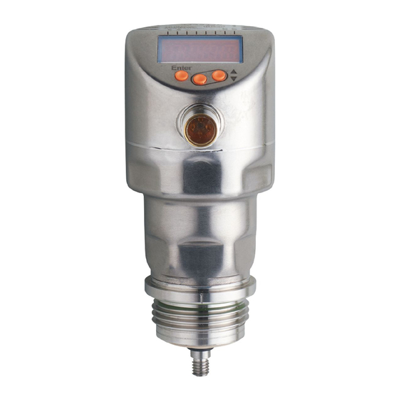
9 Operating and display elements 1 to 8: Indicator LEDs LEDs 1 - 3 Selected unit of measurement. LEDs 4 - 6 Not connected. LED 7 Switching status OUT2 (lights when output 2 is switched). LED 8 Switching status OUT1 (lights when output 1 is switched). 9: [Enter] button - Open the user menu, edit and confirm the parameter values. -
Page 25: Menu
10 Menu 10.1 Menu structure inch Menu items highlighted in grey, e.g. [ SP2 ], are only active after selection of the assigned parameters (→ 10.2.1). Main menu (→ 10.2.1) EF level (→ 10.2.2) - Page 26 Menu items highlighted in grey e.g. [ dS2 ], are only active after selection of the assigned parameters (→ 10.2.3). III : CFG level (→ 10.2.3) ENV level (→ 10.2.4) SIM level (→ 10.2.5)
-
Page 27: Explanation Of The Menu
10.2 Explanation of the menu 10.2.1 Main menu tREF Carry out tank adjustment. SP1 / rP1 Upper / lower limit value for the level at which OUT1 switches. FH1 / FL1* Upper / lower limit for the acceptable range (monitored by OUT1). ASP2 Analogue start point for level: Measured value at which the analogue start value is provided. -
Page 28: Cfg Level (Configuration)
10.2.3 CFG level (configuration) Output function for OUT1: • switching signal for level limit value. Hysteresis or window function, normally closed or normally open Output function for OUT2: • analogue signal for current level, 4…20 mA or 20…4 mA • switching signal for level limit value. Hysteresis or window function, normally closed or normally open Switching delay for OUT1 Switch-off delay for OUT1... -
Page 29: Parameter Setting
11 Parameter setting During parameter setting the unit remains in the operating mode. It continues to monitor with the existing parameters until the parameter setting has been completed. 11.1 Parameter setting in general 3 steps must be taken for each parameter setting: Select the parameter ►... - Page 30 If [C.Loc] is displayed when an attempt is made to modify a parameter value, a parameter setting process is active via IO-Link (temporary locking). If [S.Loc] is displayed, the sensor is permanently locked via software. This locking can only be removed with a parameter setting software. •...
-
Page 31: First Set-Up (Unit With Factory Setting)
For unlocking: ► Press [▲] + [▼] simultaneously for 10 s. > [uLoc] is displayed. 10 s On delivery: not locked. • Timeout: If no button is pressed for 30 s during parameter setting, the unit returns to the operating mode with unchanged values. 11.2 First set-up (unit with factory setting) On delivery of the unit, you must first enter the probe length. -
Page 32: Carry Out Tank Adjustment
11.2.2 Carry out tank adjustment ► Note the remarks (→ 7.1.2). ► Select [tREF]. ► Press [Enter]. > [nonE] or the value stored by the last tank adjustment (distance value) is displayed. ► Press [▲] or [▼] for min. 1 s. >... -
Page 33: Setting Of Output Signals
11.4 Setting of output signals 11.4.1 Setting of the output function for OUT1 ► Select [ou1] and set the switching function: [Hno] = hysteresis function / normally open [Hnc] = hysteresis function / normally closed [Fno] = window function / normally open [Fnc] = window function / normally closed Note: If the upper switch point is used as an overflow protection, the setting... -
Page 34: Setting Of Switching Limits (Window Function)
11.4.5 Setting of switching limits (window function) ► Make sure that for [oux] the function [Fno] or [Fnc] is set. ► Select [FH1] and set the upper limit of the acceptable range. ► Select [FL1] and set the lower limit of the acceptable range. [FLx] is always lower than [FHx]. -
Page 35: Setting The Delay Time For Cases Of Fault
11.4.11 Setting the delay time for cases of fault ► Select [dFo] and set a value between 0.0 and 10.0 s. Factory setting: [dFo] = [3.0]. The delay time is only effective on case of a fault. Mind the dynamics of your application. In case of fast level changes it is recommended to adapt the value step by step (→... -
Page 36: Setting To Another Medium
11.6.2 Setting to another medium ► Select [MEdI] and set: [HIGH] = For water and water-based media. Operating mode is optimised for suppression of deposits on the rod. [MId] = For water-based media and media with a medium DC value (DC = dielectric constant), e.g. -
Page 37: Operation
Simulation active until [Enter] is pressed again or the time set via [STim] elapses. During the simulation [SIm] is displayed every 3 s. When the simulation has ended, [S.On] is displayed. The outputs react according to the simulated process values. 12 Operation After power on, the unit is in the operating mode (= normal operating mode). -
Page 38: Reading The Set Parameters
12.2 Reading the set parameters ► Briefly press [Enter] to open the menu ► [▲] or [▼] scrolls through the parameters. ► Briefly press [Enter] to indicate the corresponding parameter value for about 30 s. Then the unit returns to the operating mode. 12.3 Change the display unit in the operating mode (= switching between length indication (mm / inch) and percentage). -
Page 39: Output Response In Different Operating States
ON for FOU1 = On 21 mA at FOU2 = On *) When the analogue function [ou2] = [I] is selected 13 Technical data Technical data and scale drawing at www.ifm.com → New search → Enter the article number. Setting ranges [LEnG]... -
Page 40: Maintenance / Transport
Check sealing ring(s) for damage. If sealing rings are damaged: ► Replace damaged parts (www.ifm.com → New search → Enter the article number → Accessories). When the medium is changed, it may also be necessary to adapt the unit settings (→... -
Page 41: Factory Setting
LEnG nonE MEdl S.LVL 50% LEnG S.Tim S.ON * VMR = final value of the measuring range = LEnG value minus 30 (in millimetre) When the LEnG value is entered, the program calculates the basic setting. More information at www.ifm.com...
Need help?
Do you have a question about the efector160 LR2750 and is the answer not in the manual?
Questions and answers