Table of Contents
Advertisement
The TZEMT500 Thermostat is compatible with single and
multistage forced air systems, including:
• Gas furnace systems
• Oil furnace systems
• Electric furnace systems
• Heat pump systems
• Air conditioning systems
The TZEMT500 Thermostat may be compatible with some
other system types, including:
• Boiler systems
• Geothermal systems
• Multi-zoned systems
The TZEMT500 Thermostat is not compatible with the
following system types:
• Radiant floor systems
• Wall heating systems
• Propritary HVAC Communication Protocols
The TZEMT500 Thermostat is not compatible with dual
fuel systems (gas or oil furnace & heat pump combined)
without adding a special kit. See Note below.
NOTE:
This thermostat is not compatible with dual
fuel systems (heating system with both heat pump and
gas or oil furnace), unless the system is controlled with
a dual fuel accessory relay kit.
NOTE:
A 24 Volt common and hot wire MUST be
connected to the TZEMT500 for operation.
1
WARNING
Voltage hazard. Can cause electrical shock or equipment damage. Disconnect power to
heating and cooling equipment before beginning installation.
2
Remove the existing thermostat cover from the wall plate.
Leave wires attached.
Consult instructions that came with existing thermostat as needed.
MERCURY NOTICE
When this control is replacing an old control that contains mercury in
a sealed tube, do not dispose of your old control in the trash. Dispose
of properly. Contact your local waste management authority for
instructions regarding recycling and proper disposal of the old control.
A listing of heating, ventilating and air conditioning wholesalers that
participate in the Thermostat Recycling Corporation's recycling
program are available at www.thermostat-recyle.org .
Thermostat
Model TZEMT500AB32MAA
Installation Instructions
Schlage LiNK
Customer Service: (877) 288-7707
TM
Physical Installation and Wiring
Table of Contents
18-HD39D1-1
Pages 1-11
Pages 7-9
Page 10
Pages 12-13
Pages 14
TM
System
Pages 15-16
Page 17
Pages 18-19
Page 20
Pages 21-28
Pages 29-31
Pages 32-34
Page 34
Wall plate
Thermostat cover
The look of the existing
thermostat may vary
1
Advertisement
Table of Contents

Related Manuals for Trane SCHLAGE LINK TZEMT500AB32MAA


Summary of Contents for Trane SCHLAGE LINK TZEMT500AB32MAA
-
Page 1: Table Of Contents
18-HD39D1-1 Thermostat Model TZEMT500AB32MAA Installation Instructions Schlage LiNK Customer Service: (877) 288-7707 The TZEMT500 Thermostat is compatible with single and multistage forced air systems, including: • Gas furnace systems • Oil furnace systems • Electric furnace systems • Heat pump systems •... - Page 2 Identify the existing HVAC System Type from the list below. Indoor Unit Type System Type □ Gas Furnace □ Single Stage Gas Furnace □ 1 Stage Cooling □ Multi Stage Gas Furnace □ 1 Stage Cooling □ 2 Stage Cooling □...
- Page 3 Connect a 24 VAC common wire to power the thermostat. (Continued) c. Find the 24 VAC common terminal identified with e. Find a wire from the thermostat bundle that is the letter C, X, B, or COM. unused at the thermostat and at the air handler �...
- Page 4 24RH W2/O/B New Thermostat Terminals Chart 2: Heat Pump Some wire terminals may not be used (Single Stage or Multistage) Wire Labels Thermostat Being Replaced Trane/American Standard (Weathertron) or York Other Brands Lennox **VR Connects to New Thermostat Terminals 24RC...
- Page 5 Separate the face of the new thermostat from the wall plate. Apply pressure at two tabs on top of wall plate to release it. Tabs NOTE: It is not recommended that this Z-wave thermostat be mounted onto metal structures. Metal may adversely affect the radio frequency (RF) communication between the thermostat and the Z-wave bridge.
- Page 6 Attach all wires securely to the new thermostat. (See the Field Wiring Diagrams on the following page.) Note: A wire must be connected to “24COM” to power the thermostat. Use the information from step 11 to match the wires to the correct terminals. Use 1/8”...
-
Page 7: Field Wiring Diagrams Pages
Field Wiring Diagrams The following table can be used to find the correct field connection wiring diagram for the HVAC System Type that is being installed. Indoor Unit Outdoor Unit 1 Stage Cooling 2 Stage Cooling 2 Step Cooling 1 Stage Heat Pump 2 Stage Heat Pump 2 Step Heat Pump 1 or 2 Stage Gas Furnace... - Page 8 Field Wiring Diagrams System Type C - PSC, Variable Speed, or Communicating Air Handler with 1 or 2 Stage/Step Heat Pump (Note 4, Note 5, Note 6, Note 7) Thermostat Connection Air Handler Outdoor Unit JP1: internal RC/RH Jumper BLUE 24VAC Common B 24VAC Common B/C Remote...
- Page 9 Field Wiring Diagrams (Isolation relay, See R1 below) System Type F - Variable Speed Oil Furnace with 2 Step Cooling (Note 6) Thermostat Connection Oil Furnace- Variable speed Outdoor Unit JP1: internal RC/RH Jumper BLUE 24VAC Common B 24VAC Common C Remote Sensors 24RC...
-
Page 10: Remote Temperature Sensors
Optional Remote Temperature Sensors Installation Wire specification (RS1 & RS2): 2 conductors, 18 gauge wire. Make sure that the sensor wires have a cable separate from the ther- mostat cable. Best results for distances of 100 feet or less. Accuracy may be affected for distances up to a maximum of 200 feet. Shielded cable is recommended for distances over 100 feet and less than 200 feet. - Page 11 If necessary, cut the internal jumper wire (JP1). If only one wire is connected If wires are connected to to either 24RC or 24RH both 24RC and 24RH as shown as shown Do NOT cut JP1 jumper Cut JP1 jumper 24RC 24RH 24RC...
-
Page 12: System Settings At Thermostat Pages
System Settings at Thermostat Set Time and Date MENU button twice. Press the Scroll up or down to Set Clock (it is the first option), then press the Select button. 11:15 AM User Settings Scroll 76 H Set Clock Filter Service 74 C Maint Service Screen Timeout... - Page 13 Gas Furnace - Multistage Mechanical Settings Press the MENU button twice. 11:15 AM Press and hold the two inner buttons for 3 seconds to view 76 H Installer Settings. 74 C System Settings and press the Select button. Scroll down to Mechanical Settings (it is the first option), then Scroll to MENU MODE...
-
Page 14: Perform System Checkout Pages
Optional Remote Temperature Sensors Installation Remote sensor input RS2 can be configured for use as indoor or outdoor temperature sensing. The factory default setting for RS2 is “IN” for use with remote indoor temperature sensing and/or averaging. To configure RS2 to sense outdoor temperature, complete the following steps: a. -
Page 15: Enroll Thermostat Into Schlage Link
Enroll Thermostat into Schlage LiNK System Prepare the bridge for enrollment. Unplug Ethernet and power cables from bridge. Verify that blue light is blinking. If blue light is solid, battery is dead. Install a quality 9 volt battery. Take bridge to the location where the thermostat is mounted. Blue light Battery... - Page 16 NOTE: Z-Wave™ controllers from various manufacturers may support the Z-Wave™ Thermostat General V2 Device class used by the Trane Z-Wave™ Thermostat. If you are using a controller that is not a Schlage bridge, consult the instructions that came with the controller to find out how to enroll a new device.
-
Page 17: Product Specifications
Product Specifications Specification Description Product Model: TZEMT500AB32MAA Product: Thermostat for Heating and Cooling HVAC System control. Z-Wave™ RF communications enabled Thermostat Size: 5.7” wide x 4.0” height x 1.2” depth Display: Graphical LCD, 2.75” x 1.5”, 64x128-pixel Backlight: Yes, Blue/white, Controllable, on, off, timeout Contrast: Adjustable on screen Buttons:... -
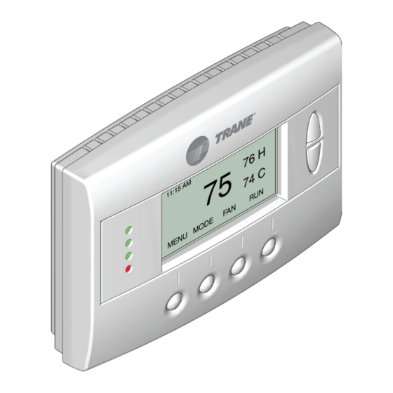
Page 18: Operation Pages
Operation The model TZEMT500AB32MAA thermostat provides typical thermostat control of a central heating and cooling HVAC system. This thermostat also features a Z-Wave™ module for remote control. Tempurature Display Clock Display 11:15 AM Sys O Setpoint 77 H Up/Down Buttons Status Indicator 74 C LEDs... - Page 19 Thermostat Control Screen Function Control Buttons 11:15 AM Sys Off 77 H 74 C Filter AUTO AUTO MENU MODE Menu Button System Fan Mode Schedule Mode Button Button Mode Button Button Description Menu Other thermostat menus can be accessed by pressing the MENU button.
-
Page 20: Menu Maps
Menu Maps MENU Installer settings are accessed by pressing the MENU User settings are accessed by pressing the button on the main screen then pressing and holding the button on the main screen. two middle buttons until the Installer Settings appear. Menu Selection User Settings Installer Settings (Hidden) -
Page 21: User Settings Pages
User Settings Set Clock The Set Clock screen allows you to set the thermostat’s internal clock. If the clock has been reset by an extended power outage, the clock display on the thermostat screen will blink. Press the Î MENU button to go directly to the Set Clock screen. Set Clock Time 11 : 15 AM... - Page 22 Filter Service The Filter Service screen will show the accumulated Filter Runtime hours as well as the Service Interval that will be used to trig- ger a Filter Message. Any type of HVAC operation that causes the HVAC system fan to run will cause the Filter Runtime value to increase.
- Page 23 Maint Service The Maintenance Service screen shows the accumulated Heat and Cool Runtime hours as well as the Service Interval that will be used to trigger a Maintenance Message. Any HEAT or COOL type of HVAC operation will cause the respective Runtime values to increase.
- Page 24 Screen Timeout This is the time before any screen reverts to the Minimized Screen (temperature display only), after you stop pushing buttons. Minimized Screen feature is disabled by setting this time to “0”. User Settings Set Clock Filter Service Maint Service Screen Timeout Done Select...
- Page 25 F/C Settings The F/C Settings screen is use to select the temperature display mode. Fahrenheit (F) or Celsius (C) are the two available modes. F/C Settings F/C Mode Done Change the Temperature Mode Press the MENU button. User Settings Select Scroll to and press the button.
- Page 26 Backlite/Display The Backlite/Display screen is used to set the backlight time-out and contrast. Backlite Timeout is the time (in seconds) from the last button press to the backlight going out. The time-out can be set between zero (0) and one hundred and twenty (120) seconds. Thirty (30) is the default setting. When set to zero (0), the backlight will remain always on.
- Page 27 Usage Graph The Usage Graph shows daily heating and cooling runtime hours for a week. Heating time (Hrs) Tue Wed Thu Fri Sat Done Cool The button in the lower right corner will change depending on what is being displayed. When the heating time is displayed, the button will read Cool.
- Page 28 Thermostat Info The Thermostat Info screen displays information about the thermostat and the system the thermostat controls. This information will be helpful if you need to contact customer support. Thermostat Info TZEMT500AB32 Ver: 01.00.13 ZVER: 02.00.9 ZNID: 004 ZHID: 01.07.37.bd System Type: Standard Fan Type:...
-
Page 29: Installer Settings Pages
Installer Settings The Installer Settings screen is a hidden screen designed for installer use only. Do not change any settings in this Î screen unless you are a qualified service technician. Installer Settings Display Lock System Settings Max Heat SP Min Cool SP Done Î... - Page 30 System Settings Changing these settings will affect the operation of the heating/cooling system. Î To view and edit these settings: Press the MENU button. Press and hold the two middle buttons simultaneously until the Installer Settings menu is displayed. Select Scroll to System Settings and press the button.
- Page 31 Mechanical Settings Î Changing these settings will affect the operation of the heating/cooling system. To view and edit these settings: MENU Press the button. Installer Settings Press and hold the two middle buttons simultaneously until the menu is displayed. Scroll to System Settings and press the Select...
-
Page 32: Schedules Pages
Schedules Scheduling is usually controlled by your Z-Wave system. See the instructions that came with your Z-Wave system for more informa- tion. However, scheduling may also be controlled by the thermostat. The Schedules menu is hidden by default, but may be enabled in the Installer Settings. See Enable/Disable the Î... - Page 33 Load a Preset Schedule There are two possible schedules that may be loaded: Preset Comfort and Preset Energy Star. These schedules may not be changed. When a schedule is loaded, it changes the current Heat and Cool schedule settings. You can then edit the Heat and Cool schedule, if necessary.
-
Page 34: Led Reference
Copy a Day Schedule Press the MENU button. Scroll to Schedules and press the Select button. Scroll to Heat and Cool and press the Select button. The day of the week is displayed at the top of the screen. Press the Next button until the day you want to copy is displayed. Highlight the small in the lower right corner by pressing the left arrow () button once. - Page 35 Parts will be provided by our factory organization through an authorized service organization in your area listed in the yellow pages. If you wish further help or information concerning this limited warranty, contact: Residential Systems 6200 Troup Highway Tyler, TX 75707 Attention: Consumer Relations Or visit our website: www.trane.com/residential TW-1019-5109...
- Page 36 Literature Order Number 18-HD39D1-1 File number 18-HD39D1-1 Trane Supersedes 6200 Troup Highway Date 1/10 Tyler, TX 75707 www.trane.com Trane has a policy of continuous product and product data improvement and it reserves the right to change design and specifications without notice.
Need help?
Do you have a question about the SCHLAGE LINK TZEMT500AB32MAA and is the answer not in the manual?
Questions and answers