Triton OMNICARE Manual
Sr pumped shower
Hide thumbs
Also See for OMNICARE:
- Installation and operating instructions manual (36 pages) ,
- Manual (36 pages)
Table of Contents
Advertisement
OMNICARE
pumped shower
SR
REGISTER ONLINE
ENTER A PRIZE DRAW
WIN
£100
LOVE2SHOP VOUCHERS
VISIT OUR WEBSITE TODAY
TRITONSHOWERS.CO.UK/REGISTER
PRODUCT REGISTRATION IS ONLY AVAILABLE
THIS OFFER IS NOT VALID OUTSIDE THE UK
TO UNITS PURCHASED & INSTALLED IN THE UK
FOR YOUR SERVICE REFERENCE
NOTE DOWN THE PRODUCT CODE BELOW
(FROM THE FRONT OR TOP OF THE BOX)
ALTERNATIVELY REGISTER BY TEL: 024 7637 8321
Under *NO circumstances must this shower be connected directly
to a mains water supply. It is designed for GRAVITY FED
INSTALLATION AND OPERATING INSTRUCTIONS
Please read this book thoroughly and familiarise yourself with all instructions before commencing
installation and keep it for future reference.
The shower installation MUST be carried out by a suitably qualified person, in the sequence of
this instruction book.
! IMPORTANT !
COLD WATER systems ONLY !
*Failure to comply may invalidate product warranty
2181655A - March 2022
IMPORTANT SAFETY ADVICE
The shower unit MUST BE switched off at the
isolating switch when not in use. This is a
safety procedure recommended for all
electrical appliances.
The shower head and hose supplied with this
product are a safety critical part of your shower.
Failure to use genuine Triton parts may cause
injury and invalidate your guarantee.
Advertisement
Table of Contents

Related Manuals for Triton OMNICARE


Summary of Contents for Triton OMNICARE
- Page 1 The shower head and hose supplied with this product are a safety critical part of your shower. Failure to use genuine Triton parts may cause injury and invalidate your guarantee. ALTERNATIVELY REGISTER BY TEL: 024 7637 8321 ! IMPORTANT ! Under *NO circumstances must this shower be connected directly to a mains water supply.
-
Page 2: Important Safety Information
INTRODUCTION - PLEASE READ PLEASE READ THIS IMPORTANT SAFETY INFORMATION Products manufactured by Triton are safe and without risk provided they are installed, used and maintained in good working order in accordance with our instructions and recommendations. ARNING: DO NOT operate shower if frozen, or suspected of being frozen. - Page 3 DO NOT operate the unit if the showerhead or spray hose becomes damaged. DO NOT restrict ow out of shower by placing showerhead in direct contact with your body. DO NOT operate the shower if water ceases to ow during use or if water has entered inside the unit because of an incorrectly tted cover.
-
Page 4: Introduction
Important: To comply with BEAB Care mark requirements the unit must not be able to run hotter than 41°C (this is used when in healthcare or special needs environments). The Omnicare SR Pumped unit is factory set at 43°C (nominal), see page 22 on how to adjust the MAXIMUM temperature to 41°C. -
Page 5: Omnicare Models
Please see back of book for contact information. WEEE Directive – Policy Statement As a producer and a supplier of electric showers, Triton Showers is committed to the protection of the environment via our own environmental policy and compliance with the WEEE directive. -
Page 6: Table Of Contents
CONTENTS Important Safety Information............2 Introduction Advice to Users...............4 Product Fiche.................4 Omnicare Models ..............5 WEEE Policy Statement............5 Specifications................7 Main Components ...............8 Dimensions, Water and Cable Entry Points ........9 Plumbing Requirements ............10 - 11 Electrical Requirements ............12 - 13 Installation Positioning of Shower ............14 Plumbing Connections ...........15 - 16... -
Page 7: Specifications
SPECIFICATION ELECTRICAL Product GEOSRP81 XEOSRP81 Nominal Power Rating at 230V 7.8kW 8.5KW Nominal Power Rating at 240V 8.5kW Supply Fuse/Miniature Circuit Breaker 8.5kW - 40Amps (MCB) Residual Current Device (RCD) 30mA Isolation Switch 45Amp double pole isolating switch, with 3mm minimum contact gap Supply Cable Maximum is 16mm, refer to Electrical Requirements... -
Page 8: Main Components
MAIN COMPONENTS Inside the unit 8. Temperature control 15. Filter 1. Top cable/pipe entry 9. Terminal block 16. Pump power supply 2. Wall screw fixings 10. Earth connection 17. Pump 3. Cover screw fixings 11. Solenoid valve 18. Trimplate 4. Thermal safety cut-out 12. -
Page 9: Dimensions, Water And Cable Entry Points
MAIN COMPONENTS Cover Inside the cover 22. Stop/start switch 21. Front cover 23. Control printed circuit board DIMENSIONS & ENTRY POINTS 316mm 88mm Diagram Key: Water Entry Points Cable Entry Points... -
Page 10: Plumbing Requirements
INSTALLATION REQUIREMENTS PLUMBING REQUIREMENTS Refer to IMPORTANT SAFETY INFORMATION and SPECIFICATION sections before undertaking installation. Note: if the recommended dynamic pressure and flow is not available, there will be a noticeable reduction in flow from the shower head. Please avoid installations subject to regular and rapid changes in water supply pressure. If it is intended to operate the shower at pressures above the maximum or below the minimum stated, contact Customer Experience for advice. - Page 11 INSTALLATION REQUIREMENTS WARNING Fig.1 Diagrammatic view (not to scale) The shower MUST NOT be positioned where For illustration purposes only. Kits may vary. it will be subjected to freezing conditions. Cold Shower unit water supply can be mounted (either top, bottom either side or back entry) of riser rail...
-
Page 12: Electrical Requirements
Contact a professional electrician/local electricity company for advisement. 8. For close circuit protection DO NOT use a rewireable fuse. Instead use a suitably rated Miniature Circuit Breaker (MCB) or cartridge fuse. Triton recommend the following circuit protection: 8.5kW - 40Amp 9. - Page 13 INSTALLATION REQUIREMENTS 10. A 45 amp double pole isolating switch with a minimum contact gap of 3mm in both poles must be incorporated in the circuit. It must have a mechanical indicator showing when the switch is in the OFF position, and the wiring must be connected to the switch without the use of a plug or socket outlet.
-
Page 14: Installation
INSTALLATION POSITIONING THE SHOWER For ease of servicing, the unit must always be mounted on the surface of tiled walls. Never tile up to the unit. Position the unit where it will not be in direct contact with water from the shower head. Mount the shower unit vertically. -
Page 15: Plumbing Connections
INSTALLATION Step Step Rotate inlet fitting to suit the required water supply pipe entry position* *Take care not to trap or tangle earth wire on the inlet fitting Bottom Entry Top Entry Rear Entry PRD escape vent DO NOT BLOCK OR SEAL! Step Step - Complete all the plumbing pipework. -
Page 16: Fixing To Wall
INSTALLATION Step Step Hole Hole Hole Hole - Temporarily connect the shower to plumbing pipework. - Using the backplate as a template, making sure it is level, mark the fixing holes. Use hole 1 & 2 at the top and the 2 holes at the bottom to secure the shower. - Remove the shower from the wall. -
Page 17: Electrical Connections
INSTALLATION Step Step Earth cable (Green/Yellow) to Neutral cable (Blue or Black) to - Route the electrical supply cable into the Live cable (Brown or Red) to shower unit. Note: The supply cable must be secured either Terminal block by routing through conduit, trunking or by embedding in the wall, in accordance with IEE regulations. -
Page 18: Shower Drain Pumps (Not Supplied)
When the shower is turned off, a signal is sent again to the drain pump electronics telling The Omnicare SR Pumped has been designed the pump to stop; generally after a preset time to operate with the most popular analogue delay. -
Page 19: Pcb Dip Switch Settings
INSTALLATION Step Step 1 2 3 Dip Switch Settings A four way DIP switch block is mounted on the control PCB that allows the user to configure the shower to perform different functions. Dip Switch No. Operation Enabled Switch Position DIP switch 1 On Audible Feedback On (Factory setting) -
Page 20: Commissioning
INSTALLATION Step Step COMMISSIONING Make sure that the electricity supply to the unit and isolating switch has been turned off before proceeding. Step Step Remove the front cover and disconnect the PCB cable from the rear cover PCB then remove the right hand trimplate. - Page 21 INSTALLATION Step Step COMMISSIONING Step Step Refit the trimplate and the cover with two of the four retaining screws. DO NOT reconnect the ribbon cable to the cover PCB at this time. Attach the appropriate end of the shower hose to the shower outlet using the supplied hose Step Step and washer seal - DO NOT overtighten.
-
Page 22: Adjusting The Maximum Temperature Stop
INSTALLATION Step Step ADJUSTING THE MAXIMUM TEMPERATURE STOP (If you’re not adjusting the maximum temperature then this step may be ignored) ‘ Step Step The temperature control valve has an adjustable maximum temperature stop 10-1 mechanism that is supplied factory set at MAX temp (43°C approx.). Step Step To select a lower maximum temperature stop setting, isolate the mains electricity supply... -
Page 23: Beab Care
INSTALLATION Step Step IMPORTANT INFORMATION: BEAB Care *BEAB Care mark specification states a MAXIMUM of 41°C outlet temperature. If the shower is adjusted above the maximum 41°C the product falls outside the official BEAB Care mark specification. Setting the Temperature Stop to *41ºC BEAB Care Step Step 11-1... -
Page 24: Fitting The Cover
INSTALLATION Step Step Connect the 6-way cable from the Unit to the cover PCB. Note: The cable connector can be fitted to the socket only one way. Step Step Guide the cover into position so that the temperature selector locates correctly onto the valve (minor adjustment of the temperature dial may be necessary to align with the valve). -
Page 25: Operating Instructions
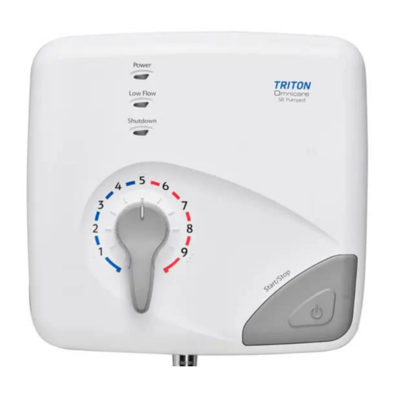
OPERATING INSTRUCTIONS When the electricity supply to the shower is switched on Power On indicator at the isolating switch, the power indicator will light. Low Flow indicator To Start the Shower Timed Shutdown Press the start/stop button indicator and water will flow. After a few seconds a flow of heated water will be available. - Page 26 OPERATING INSTRUCTIONS To Adjust the Shower Temperature The water temperature is altered by changing the amount of Hot water from the heater can that is mixed with Cold water from the inlet. This is done by moving the temperature control lever.
- Page 27 OPERATING INSTRUCTIONS Note: It is advisable to be To Decrease the certain that the showering Shower Temperature temperature is satisfactory Turn the temperature by testing with your hand control anti-clockwise; this before stepping under the will increase the flow of shower head.
- Page 28 OPERATING INSTRUCTIONS Low Flow Indicator on how to program the (red) unit. If a low flow condition occurs the unit will turn off *Note the water flow immediately. The timed shutdown It will be necessary to wait indicator will only until water in the unit has operate if the unit reduced to a comfortable...
- Page 29 OPERATING INSTRUCTIONS It will require a visit Temperature Protection from a qualified During normal operation, if engineer to identify the flow of water through the nature of the fault the unit is restricted, power and replace the safety to the elements will be device.
-
Page 30: Maintenance - Cleaning The Filter
MAINTENANCE Instructions for installers and service engineers only INSTRUCTIONS FOR INSTALLERS AND SERVICE ENGINEERS ONLY Instructions for installers and service engineers only Cleaning the Filter It is recommended that the filter is periodically cleaned in order to maintain the performance of the shower. -
Page 31: Fault Finding/Troubleshooting
FAULT FINDING/TROUBLESHOOTING FAULT FINDING Important: Switch off the electricity at the mains supply and remove the circuit fuse before attempting any fault finding inside the unit. Problem Cause Action Problem/Symptom Cause Action/Cure 1 Shower inoperable, no 1.1 Interrupted power 1.1.1 Blown fuse or circuit breaker. - Page 32 FAULT FINDING/TROUBLESHOOTING FAULT FINDING Problem/Symptom Problem Cause Cause Action/Cure Action 7 Low flow LED comes 7.1 Low flow condition 7.1.1 Shower will not start until water in the unit has on when shower is has caused cooled and LED goes off. If problem persists. running.
-
Page 33: Maintenance - Beab Care
MAINTENANCE - BEAB CARE Important: These tests should only be performed by a qualified engineer. Commissioning and In-Service Tests Commissioning D.1.1 Purpose Since the installed supply conditions are likely to be different from those applied in production it is appropriate, at commissioning, to carry out some simple checks and tests on each instantaneous water heater to provide a performance reference point for future in-service tests. - Page 34 MAINTENANCE - BEAB CARE D.2.2 Procedure D.2.3 Using the measuring equipment recorded in D.1.4 or equipment to the same specification and with the appliance turned off check that: The water supply temperature is within the range 5 to 20°C; The terminal voltage at the appliance is within the range 230 ± 10% D.2.4 If the set maximum outlet water temperature has changed significantly from the previous test results (e.g.
-
Page 35: In-Service Commissioning & Testing
MAINTENANCE - BEAB CARE D.3.1.1 6 to 8 weeks after commissioning, conduct the tests detailed in D.2.2 to D.2.6. D.3.1.2 12 to 15 weeks after commissioning, conduct the tests given in D.2.2 to D.2.6. D.3.1.3 Depending on the results of D.3.1.1 and D.3.1.2 several possibilities exist: If no significant changes (e.g. - Page 36 COMMISSIONING RECORD...
- Page 37 IN SERVICE TESTING RECORD...
- Page 38 Note: The service valve should be returned If, after making the above checks, an to the fully open position after this test. acceptable outlet water temperature is not achieved withdraw the shower from service and contact Triton Customer Experience on 024 7637 2222.
-
Page 39: Spares
OMNICARE SR PUMPED In-service Testing Omnicare SR Pumped Designation Code: -IW-S Shower SPARES To purchase a genuine Triton spare part for your product, please visit www.tritonshowers.co.uk/spares for product codes and prices. Alternatively please call our Customer Experience team on 024 7637 2222 to order direct. -
Page 40: Service Policy / Guarantee, Etc
Trade Installer Hotline: 024 7637 8344 Nuneaton www.tritonshowers.co.uk Warwickshire, CV11 4NR E-mail: serviceenquiries@tritonshowers.co.uk E-mail: technical@tritonshowers.co.uk Triton is a division of Norcros Group (Holdings) Limited Triton reserve the right to change product specifi cation without prior notice. E&OE. © TRITON SHOWERS 2022...
Need help?
Do you have a question about the OMNICARE and is the answer not in the manual?
Questions and answers