Table of Contents
Advertisement
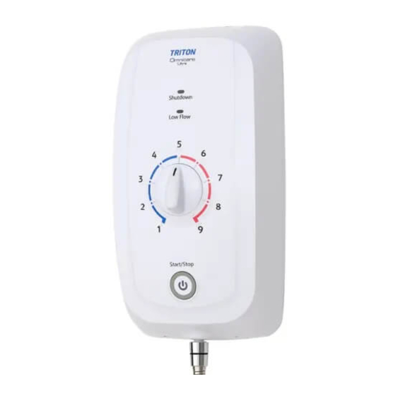
OMNICARE ULTRA
Elec tric Shower
REGISTER ONLINE
ENTER A PRIZE DRAW
WIN
£100
LOVE2SHOP VOUCHERS
VISIT OUR WEBSITE TODAY
TRITONSHOWERS.CO.UK/REGISTER
PRODUCT REGISTRATION IS ONLY AVAILABLE TO
UNITS PURCHASED & INSTALLED IN THE UK
FOR YOUR SERVICE REFERENCE
NOTE DOWN THE PRODUCT CODE BELOW
(FROM THE FRONT OR TOP OF THE BOX)
ALTERNATIVELY REGISTER BY TEL: 024 7637 8321
INSTALLATION AND OPERATING INSTRUCTIONS
Please read this book thoroughly and familiarise yourself with all instructions before commencing
installation and keep it for future reference.
The shower installation MUST be carried out by a suitably qualified person, in the sequence of
this instruction book.
Design Registration:
EU - 008265516
UK - 6108473
IMPORTANT SAFETY ADVICE
Failure to use genuine Triton parts may cause
injury and invalidate your guarantee.
The shower unit MUST BE switched off at the
isolating switch when not in use. This is a safety
procedure recommended for all electrical
appliances.
2181638B - March 2021
Advertisement
Table of Contents

Related Manuals for Triton OMNICARE ULTRA


Summary of Contents for Triton OMNICARE ULTRA
- Page 1 NOTE DOWN THE PRODUCT CODE BELOW IMPORTANT SAFETY ADVICE (FROM THE FRONT OR TOP OF THE BOX) Failure to use genuine Triton parts may cause injury and invalidate your guarantee. The shower unit MUST BE switched off at the isolating switch when not in use. This is a safety procedure recommended for all electrical appliances.
- Page 2 PLEASE READ THIS IMPORTANT SAFETY INFORMATION Products manufactured by Triton are safe and without risk, provided they are installed, used and maintained in good working order in accordance with our instructions and recommendations. WARNING : DO NOT operate the shower if there is a possibility of frozen water within the heater or pipes feeding the shower.
- Page 3 IMPORTANT GUIDANCE NOTES PLEASE READ BEFORE PROCEEDING GENERAL 2.3 Do NOT solder fittings near the shower unit as Isolate the electrical and water supplies before heat can travel along pipework and damage removing the cover. components. Read all of these instructions and retain them 2.4 DO NOT fit any form of outlet flow control as for later use.
-
Page 4: Introduction
Important: To comply with BEAB care mark requirements the unit must not be able to run hotter than 41°C (this is used in healthcare or special needs environments). The Omnicare Ultra thermostatic unit is factory set at 43°C (nominal), see page 21 on how to adjust the MAXIMUM temperature to 41°C At a selected showering temperature the unit will provide the optimum flow rate possible. -
Page 5: Omnicare Ultra Models
Please see back of book for contact information. WEEE Directive – Policy Statement As a producer and a supplier of electric showers, Triton Showers is committed to the protection of the environment via our own environmental policy and the compliance with the WEEE directive. -
Page 6: Table Of Contents
CONTENTS Page Important Safety Information ............Introduction Advice to Users ................ Product Fiche ................Omnicare Ultra Models ............WEEE Policy Statement............. Specifications.................. Main Components ................. Dimensions, Water and Cable Entry Points ........Electrical .................. Plumbing ................Installation Requirements Plumbing ................ -
Page 7: Specifications
SPECIFICATION ELECTRICAL Nominal Power Rating at 230V 8.0kW 9.0kW Nominal Power Rating at 240V 8.7kW 9.8kW 8.7kW - 40Amps Supply Fuse/Miniature Circuit Breaker (MCB) 9.8kW - 45Amps Residual Current Device (RCD) 30mA Isolation Switch 45Amp Double Pole Isolating Switch, with 3mm Minimum Contact Gap Supply Cable Maximum is 16mm, Refer to ‘Electrical Requirements’... -
Page 8: Main Components
MAIN COMPONENTS Inside the unit Inside the Cover 1. Top cable and pipe entry 8. Can and element assembly Water inlet 2. Bottom cable and pipe entry 9. Pressure switch Pressure relief device (PRD) 3. Rear cable and pipe entry 10. - Page 9 SPECIFICATION DIMENSIONS & ENTRY POINTS 213mm 117mm Diagram Key: Water Entry Points 213mm 116mm Electrical Cable Entry Points...
- Page 10 INSTALLATION REQUIREMENTS PLUMBING REQUIREMENTS Refer to IMPORTANT SAFETY INFORMATION and SPECIFICATION sections before undertaking installation. Note: if the recommended dynamic pressure and flow is not available, there will be a noticeable reduction in flow from the showerhead. If it is intended to operate the shower at pressures above the maximum or below the minimum stated, contact Customer Experience for advice.
-
Page 11: Installation Requirements
INSTALLATION REQUIREMENTS WARNING Fig.1 Diagrammatic view (not to scale) The shower MUST NOT be positioned where For illustration purposes only. Kits may vary. it will be subjected to freezing conditions. Mains cold water supply Shower unit (either top, bottom can be mounted or rear entry) either side of riser rail... -
Page 12: Electrical
Contact a professional electrician/ local electricity company for advisement. 8. For close circuit protection DO NOT use a rewireable fuse. Instead use a suitably rated Miniature Circuit Breaker (MCB) or cartridge fuse. Triton recommend the following circuit protection: 8.7KW - 40Amp 9.8kW - 45Amp... - Page 13 INSTALLATION REQUIREMENTS 10. A 45 amp double pole isolating switch with a minimum contact gap of 3mm in both poles must be incorporated in the circuit. It must have a mechanical indicator showing when the switch is in the OFF position, and the wiring must be connected to the switch without the use of a plug or socket outlet.
-
Page 14: Installation
INSTALLATION POSITIONING THE SHOWER For ease of servicing, the unit must always be mounted on the surface of tiled walls. Never tile up to the unit. Position the unit where it will not be in direct contact with water from the showerhead. Mount the shower unit vertically. - Page 15 INSTALLATION Step Step - Temporarily connect the shower to plumbing pipework. - Using the backplate as a template (making sure it is level), mark the fixing holes. Use any 2 holes at the top and any 2 holes at the bottom to secure the shower.
- Page 16 INSTALLATION Step Step Earth cable (Green/Yellow) to Neutral cable (Blue or Black) to - Route the electrical supply cable into the Live cable (Brown or Red) to shower unit. Terminal block Note: The supply cable must be secured either by routing through conduit, trunking or by embedding in the wall, in accordance with IEE regulations.
-
Page 17: Drain Pump Connectivity
INSTALLATION Step Step DRAIN PUMP CONNECTIVITY (If no drain pump is being connected to the shower then this step can be ignored) The Omnicare has been designed to operate with the most popular drain pumps found on the market, please take time to fully understand the type of drain pump being fitted and the connection required to the shower. - Page 18 INSTALLATION Configuration 2 for Digital Drain Pumps* *Digital drain pump connection is only available on Omnicare Ultra+ Digi variants When the shower is turned on, a digital signal is sent to the drain pump electronics telling the pump to start and the pump speed required. When the shower is turned off, the digital signal stops.
-
Page 19: Shower Settings Setup
INSTALLATION Step Step SHOWER SETTINGS SETUP The Omnicare Ultra shower has some functionality settings that can be customised to individual user’s preference. A DIP switch mounted on the Power PCB allows these settings to be adjusted. Factory Settings Audible Feedback This function provides an audible notification to specific shower operations and warnings. -
Page 20: Commissioning
INSTALLATION COMMISSIONING THE SHOWER Step Step Step Step Attach the appropriate end of the shower Temporarily fit the cover to the shower. hose to the shower outlet, using the DO NOT connect the wire from the cover supplied hose washer seal. DO NOT to shower unit PCB, minor adjustment of overtighten. -
Page 21: Adjusting The Maximum Temperature Stop
INSTALLATION Step Step ADJUSTING THE MAXIMUM TEMPERATURE TO 41°C (If not adjusting the maximum temperature then this step can be ignored) The shower unit is supplied factory set to give a nominal maximum temperature of 43°C. However, the temperature selector mechanism can be adjusted to restrict the maximum temperature to 41°C. -
Page 22: Beab Care
INSTALLATION Step Step BEAB CARE* MAXIMUM TEMPERATURE (If not adjusting to BEAB Care then this step can be ignored) IMPORTANT: This process should only be performed by a qualified engineer *BEAB care mark specification states a MAXIMUM of 41°C outlet temperature. If the shower is adjusted above the maximum 41°C the product falls outside the BEAB care mark specification. - Page 23 INSTALLATION Step Step Step Step Guide the cover into position so that the temperature selector locates correctly onto the valve (minor adjustment of the Connect the 6-way cable from the cover temperature dial may be necessary to to the socket on the power PCB cable. align with the valve).
-
Page 24: Operating Instructions
OPERATING INSTRUCTIONS Switch ON the electricity supply at the isolating switch. Check that the power on indicator in the centre of the start/stop button is illuminated with a green light. Start the shower by pressing the Start/Stop button After a few seconds the water will start to flow from the showerhead. - Page 25 OPERATING INSTRUCTIONS Power On Indicator The power on indicator will Shutdown illuminate with a green light when there is an electricity indicator supply to the shower. Low flow indicator Low Flow Indicator If a low flow condition occurs Temperature during showering, the unit control will turn off the water flow immediately and illuminate...
- Page 26 OPERATING INSTRUCTIONS Phased Shutdown In use, every time the Start/Stop button is pressed, power is switched off to the elements. Water will continue to flow for a few seconds, purging any remaining hot water. This makes sure the next immediate user will not receive a slug of hot water if standing under the showerhead when starting the shower.
-
Page 27: Maintenance
MAINTENANCE Instructions for installers and service engineers only INSTRUCTIONS FOR INSTALLERS AND SERVICE ENGINEERS ONLY Instructions for installers and service engineers only Cleaning the Filter It is recommended that the filter is periodically cleaned in order to maintain the performance of the shower. It is essential that this operation is carried out by a competent person. -
Page 28: Beab Care
MAINTENANCE - BEAB CARE Important: These tests should only be performed by a qualified engineer. Commissioning and In-Service Tests Commissioning D.1.1 Purpose Since the installed supply conditions are likely to be different from those applied in production it is appropriate, at commissioning, to carry out some simple checks and tests on each instantaneous water heater to provide a performance reference point for future in-service tests. - Page 29 MAINTENANCE - BEAB CARE D.2.2 Procedure D.2.3 Using the measuring equipment recorded in D.1.4 or equipment to the same specification and with the appliance turned off check that: the water supply temperature is within the range 5 to 20°C; the terminal voltage at the appliance is within the range 230 ± 10%. D.2.4 If the set maximum outlet water temperature has changed significantly from the previous test results (e.g.
- Page 30 MAINTENANCE - BEAB CARE D.3.1.1 6 to 8 weeks after commissioning, conduct the tests detailed in D.2.2 to D.2.6. D.3.1.2 12 to 15 weeks after commissioning, conduct the tests given in D.2.2 to D.2.6. D.3.1.3 Depending on the results of D.3.1.1 and D.3.1.2 several possibilities exist: If no significant changes (e.g.
-
Page 31: Fault Finding/Troubleshooting
FAULT FINDING/TROUBLESHOOTING FAULT FINDING Important: Switch off the electricity at the mains supply and remove the circuit fuse before attempting any fault finding inside the unit. Problem Cause Action 1 Shower inoperable, no 1.1 Interrupted power 1.1.1 Blown fuse or circuit breaker. Check supply water flow. - Page 32 FAULT FINDING/TROUBLESHOOTING Problem Cause Action 5 Pressure relief device 5.1 Blocked showerhead. 5.1.1 Clean sprayplate and then fit a new PRD. has operated (water ejected from PRD 5.2 Twisted/blocked 5.2.1 Check for free passage through hose. Replace tube). flexible shower hose. hose if necessary and then fit new PRD.
-
Page 33: Spares
In the unlikely event of unit failure other than detailed in the fault finding page, please contact Customer Experience for advice. SPARES To purchase a genuine Triton spare part for your product, please visit www.tritonshowers.co.uk/spares for product codes and prices. - Page 34 Descriptive Word Document Extra Large Print Alternative format User Instructions are available for the this shower and the Remote start/stop button accessory. Should you require a copy of the alternative User Instructions please contact Triton Customer Experience on 024 7637 2222...
- Page 36 Trade Installer Hotline: 024 7637 8344 Nuneaton www.tritonshowers.co.uk Warwickshire, CV11 4NR E-mail: serviceenquiries@tritonshowers.co.uk E-mail: technical@tritonshowers.co.uk Triton is a division of Norcros Group (Holdings) Limited Triton reserve the right to change product specifi cation without prior notice. E&OE. © TRITON SHOWERS 2020...
Need help?
Do you have a question about the OMNICARE ULTRA and is the answer not in the manual?
Questions and answers