Table of Contents
Advertisement
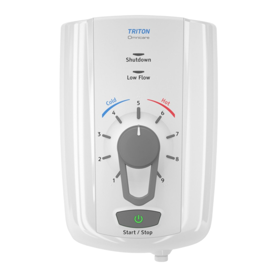
OMNICARE
Electric Shower
REGISTER ONLINE
ENTER A PRIZE DRAW
WIN
£100
LOVE2SHOP VOUCHERS
VISIT OUR WEBSITE TODAY
TRITONSHOWERS.CO.UK/REGISTER
PRODUCT REGISTRATION IS ONLY AVAILABLE
TO UNITS PURCHASED & INSTALLED IN THE UK
FOR YOUR SERVICE REFERENCE
NOTE DOWN THE PRODUCT CODE BELOW
(FROM THE FRONT OR TOP OF THE BOX)
ALTERNATIVELY REGISTER BY TEL: 024 7637 8321
INSTALLATION AND OPERATING INSTRUCTIONS
Please read this book thoroughly and familiarise yourself with all instructions before commencing
installation and keep it for future reference.
The shower installation MUST be carried out by a suitably qualified person, in the sequence of
this instruction book.
IMPORTANT SAFETY ADVICE
Failure to use genuine Triton parts may cause
injury and invalidate your guarantee.
The shower unit MUST BE switched off at the
isolating switch when not in use. This is a safety
procedure recommended for all electrical
appliances.
2181639C - March 2021
UK Patent
GB2522438
Advertisement
Table of Contents


Need help?
Do you have a question about the Omnicare and is the answer not in the manual?
Questions and answers
Ok, thank you. How do I adjust the riser rail? There are no screws.
The Triton Omnicare shower includes a 680mm riser rail kit with adjustable fixing centres, allowing you to adjust the rail to suit your comfort and requirements. This design ensures flexibility in positioning the showerhead for ease of use.
This answer is automatically generated
@Mr. Anderson
How do I access the adjustable fixing centre. I have taken the cover off and there are no screws to undo. The riser rail is solid, how do I loosen it to raise it so that I can position the soap dish? Thank you for your help.
How do I move the riser rail up & down?
The Triton Omnicare riser rail is adjustable in height, making it easier to shower while seated or standing. The shower head holder is height adjustable, and the grab riser rail is designed to support a load of up to 150kg. To adjust the riser rail, use the single-hand operated handset holder with the easy push system to move the shower head to the desired height.
This answer is automatically generated
How do I access the adjustable fixing centre to raise the rail upwards.
To access the adjustable fixing centre on the Triton Omnicare and raise the rail upwards, you need to loosen the machine screws slightly so the rail is not fully tightened. This allows adjustment. Once positioned correctly, tighten both screws securely.
This answer is automatically generated
How do I adjust the riser rail so that I can put a soap holder dish on it. The installer told me there was no soap/gel holder with the one i bought.
The Triton Omnicare riser rail comes with a height-adjustable shower head holder. To install a soap holder dish, you would need to adjust the riser rail by loosening the holder mechanism, positioning the soap dish at the desired height, and then securing it in place. The rail’s design allows for easy adjustments to accommodate accessories like a soap holder dish.
This answer is automatically generated
Hi, I have a Triton Omnicare shower and didn’t install it for a while. When I came to install it I have found that I don’t have the corner pieces or the 2 screws to fix the cover. Is it possible to get replacements for these please?
YES. Replacement parts such as corner pieces (referred to as pipe entry trims) and screws for the Triton Omnicare shower are available. For example, the top pipe entry trim (Ref. 1, product code 7054869) and bottom pipe entry trim (Ref. 2, product code 7054870) can be purchased. These trims are priced at £12.75 each.
This answer is automatically generated