Table of Contents
Advertisement
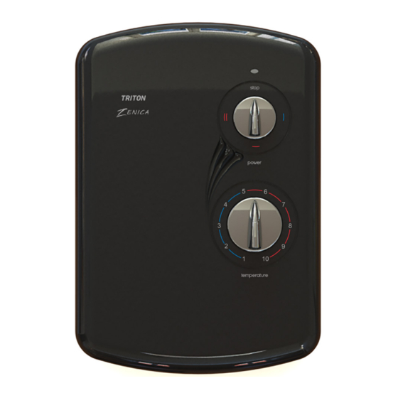
Z E N IC A
electric shower
REGISTER ONLINE
ENTER A PRIZE DRAW
WIN
£100
LOVE2SHOP VOUCHERS
VISIT OUR WEBSITE TODAY
TRITONSHOWERS.CO.UK/REGISTER
PRODUCT REGISTRATION IS ONLY AVAILABLE
THIS OFFER IS NOT VALID OUTSIDE THE UK
TO UNITS PURCHASED & INSTALLED IN THE UK
FOR YOUR SERVICE REFERENCE
NOTE DOWN THE PRODUCT CODE BELOW
(FROM THE FRONT OR TOP OF THE BOX)
ALTERNATIVELY REGISTER BY TEL: 024 7637 8321
INSTALLATION AND OPERATING INSTRUCTIONS
Please read this book thoroughly and familiarise yourself with all instructions before commencing
installation and keep it for future reference.
The shower installation MUST be carried out by a suitably qualified person, in the sequence of
this instruction book.
IMPORTANT SAFETY ADVICE
The shower unit MUST BE switched off at the
isolating switch when not in use. This is a
safety procedure recommended for all
electrical appliances.
The shower head and hose supplied with this
product are a safety critical part of your shower.
Failure to use genuine Triton parts may cause
injury and invalidate your guarantee.
2181530D - April 2021
Advertisement
Table of Contents


Need help?
Do you have a question about the ZENICA 8.5kW and is the answer not in the manual?
Questions and answers
My trition zenica electric shower isn't getting any hot water