Multitech Conduit AP Hardware Manual
Hide thumbs
Also See for Conduit AP:
- User manual (35 pages) ,
- Hardware manual (30 pages) ,
- User manual (30 pages)
Table of Contents
Advertisement
Quick Links
Advertisement
Table of Contents

Related Manuals for Multitech Conduit AP


Summary of Contents for Multitech Conduit AP
- Page 1 ® Conduit MTCAP2-LNA3-915 and MTCAP2-915 Hardware Guide...
- Page 2 Legal Notices The MultiTech products are not designed, manufactured or intended for use, and should not be used, or sold or re-sold for use, in connection with applications requiring fail-safe performance or in applications where the failure of the products would reasonably be expected to result in personal injury or death, significant property damage, or serious physical or environmental damage.
-
Page 3: Table Of Contents
CONTENTS Contents Chapter 1 – Product Overview ..........................5 Overview ..................................5 Product Build Options ..............................5 Package Contents................................5 Documentation Overview ............................. 6 Developer Documentation............................6 Chapter 2 – Specifications and Hardware Information ..................... 7 Dimensions..................................7 Specifications ................................8 Power Measurements.............................. - Page 4 CONTENTS Chapter 5 – Setting Up Hardware........................... 22 Installing a SIM Card ..............................22 Removing a SIM Card..............................22 Attaching the Antenna ..............................22 Cabling the Device............................... 22 Chapter 6 – Getting Started ........................... 23 mPower Models ................................23 Dual Carrier Firmware for Cellular Radio........................23 Chapter 7 –...
-
Page 5: Chapter 1 - Product Overview
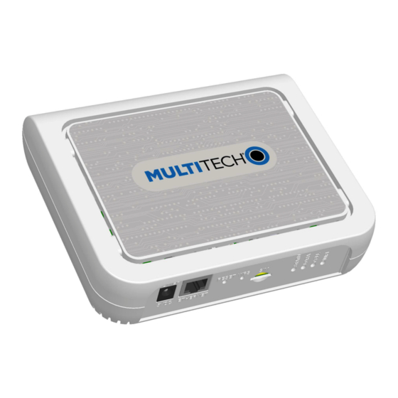
Chapter 1 – Product Overview Overview ® Conduit AP (MTCAP2) connects thousands of IoT assets to the cloud using the LoRaWAN protocol. It expands LoRa network coverage to difficult to reach areas and is capable of packet forwarding user data between LoRa end points and a centrally located network server on the cloud, in a data center, or a public network. -
Page 6: Documentation Overview
PRODUCT OVERVIEW Documentation Overview The following documents are available at http://www.multitech.com/brands/multiconnect-conduit-ap. Select your model to find the documents specific for that device. Document Description Part Number Conduit AP MTCAP2-LNA3-915 and This document. Hardware, regulatory, and S000765 MTCAP2-915 Hardware Guide getting started information. -
Page 7: Chapter 2 - Specifications And Hardware Information
SPECIFICATIONS AND HARDWARE INFORMATION Chapter 2 – Specifications and Hardware Information Dimensions ® Conduit AP MTCAP2-LNA3-915 and MTCAP2-915 Hardware Guide... -
Page 8: Specifications
SPECIFICATIONS AND HARDWARE INFORMATION Specifications Category Description General Standards LoRaWAN 1.0.2 specifications LTE 3GPP Release 9 HSPA+ 256MB Flash 256MB Radio Frequency ISM Band 915 MHz ISM band for US and Canada 4G/LTE 1900 (B2) / AWS 1700 (B4) / 850 (B5) / 700 (B12/13) 1900 (B2) / 850 (B5) Physical Description Weight... -
Page 9: Power Measurements
SPECIFICATIONS AND HARDWARE INFORMATION Power Measurements Cellular Radio Models Note: Multi-Tech Systems, Inc. recommends that you incorporate a 10% buffer into the power source when determining product load. Constant Current Mode: Voltage during charging in constant current mode was between 3.2 VDC and 4.0 VDC. -
Page 10: Connectors And Leds
SPECIFICATIONS AND HARDWARE INFORMATION Radio Protocol Battery State Cellular Average TX Pulse (AVG) Total Inrush Total Call Box Measured Amplitude Charge Inrush Connectio Current at Current for Measured in Charge n, No Data Maximum GSM850 or Millicoulombs Duration Power Peak Current During for HSDPA/LTE Power Up... - Page 11 SPECIFICATIONS AND HARDWARE INFORMATION Item Description Power 5 Volt power jack. Ethernet RJ45 Ethernet jack. Reset Reset button. Reboots device or restores factory defaults. Refer to Resetting the Device details. (No label) Connector for external LoRa antenna. Cellular models only. Micro (3FF) SIM slot. Refer to Installing SIM Card for details. LEDs STATUS Blinks when operating system is fully loaded.
-
Page 12: Resetting The Device
LoRa Antenna Manufacturer: Pulse Electronics Description: 868-928 MHz RP-SMA Antenna, 8" Model Number: W1063 MultiTech ordering information: ® Conduit AP MTCAP2-LNA3-915 and MTCAP2-915 Hardware Guide... - Page 13 SPECIFICATIONS AND HARDWARE INFORMATION Ordering Part Number Quantity AN868-915A-1HRA AN868-915A-10HRA AN868-915A-50HRA LoRa Antenna Specifications Category Description Frequency Range 868-928 MHz Impedance 50 Ohms VSWR < 2.0 Gain 3.0 dBi Radiation Omni Polarization Vertical ® Conduit AP MTCAP2-LNA3-915 and MTCAP2-915 Hardware Guide...
-
Page 14: Chapter 3 - Safety Information
A rechargeable lithium battery pack located within the product provides backup power for up to four hours. The battery pack has an estimated life expectancy of five years. The battery is not user replaceable. If it fails, the device must be sent back to MultiTech Systems for replacement. -
Page 15: Power Supply Caution
SAFETY INFORMATION UN3481 Label Power Supply Caution CAUTION: Do not replace the power supply with one designed for another product; doing so can damage the modem and void your warranty. Adapter shall be installed near the equipment and shall be easily accessible. CAUTION: Pour garantir une protection continue contre les risques d'incendie, remplacez les fusibles uniquement par des fusibles du même type et du même calibre. -
Page 16: Radio Frequency (Rf) Safety
SAFETY INFORMATION Radio Frequency (RF) Safety Due to the possibility of radio frequency (RF) interference, it is important that you follow any special regulations regarding the use of radio equipment. Follow the safety advice given below. Operating your device close to other electronic equipment may cause interference if the equipment is inadequately protected. -
Page 17: Precautions For Pacemaker Wearers
Do not place the device alongside computer discs, credit or travel cards, or other magnetic media. The information contained on discs or cards may be affected by the device. Using accessories, such as antennas, that MultiTech has not authorized or that are not compliant with MultiTech's accessory specifications may invalidate the warranty. -
Page 18: Ul Notice
SAFETY INFORMATION UL Notice UL Listed at 40° C, limited by power supply. UL Certification does not apply or extend to an ambient above 40° C and has not been evaluated by UL for ambient greater than 40° C. “UL has evaluated this device for use in ordinary locations only. -
Page 19: Chapter 4 - Labels
The label shown is not the actual size. 1 - MultiTech Model Identification. 2 - MultiTech Ordering Part Number. 3 - Ethernet MAC Address 4 - IMEI Number (cellular models only) 5 - Device Node Number... -
Page 20: Mtcap2-Lna3-043 Models
LABELS Package Label MTCAP2-LNA3-043 Models Device Label ® Conduit AP MTCAP2-LNA3-915 and MTCAP2-915 Hardware Guide... - Page 21 LABELS Package Label ® Conduit AP MTCAP2-LNA3-915 and MTCAP2-915 Hardware Guide...
-
Page 22: Chapter 5 - Setting Up Hardware
SETTING UP HARDWARE Chapter 5 – Setting Up Hardware Installing a SIM Card Models with cellular capability have a micro SIM slot, you'll need a micro (3FF) SIM card from your network provider. Note: -LNA3 models work on both Verizon and AT&T networks. The device detects the carrier based on your SIM card. -
Page 23: Chapter 6 - Getting Started
Software Guide (S000727), available through your model's page at https://www.multitech.com/brands/multiconnect-conduit-ap Dual Carrier Firmware for Cellular Radio This device uses a cellular radio with dual carrier firmware meaning that it can be used on different carrier networks (not simultaneously). The device can be used on either the Verizon or AT&T/other networks. The device is configured for AT&T/others by default. -
Page 24: Chapter 7 - Carrier Notice
MultiTech has developed a script for customers to use in order to initiate a FOTA update from the (the customer’s) local host processor (pull FOTA). MultiTech LTE Category M1, Cat 1, and Cat 4 devices for Verizon will allow the customer to initiate a FOTA update from a remote server (push FOTA) as required and communicated by Verizon. - Page 25 CARRIER NOTICE AT+CSQ Issue the following command to check for registration presence: AT+CEREG? If signal and registration are present, issue the following command to establish data connection: AT#SGACT=3,1 If signal and registration are not present, check antenna for proper connection and SIM for correct orientation.
-
Page 26: Fota Client Example Session Log
CARRIER NOTICE Note: Before deploying the device, thoroughly test your chosen FOTA implementation for functionality. Before performing any module firmware update to devices in the field, first thoroughly test the new module firmware to ensure compatibility with your existing application. In the above example you might consider placing on the FTP server one file for every IMEI you deploy. - Page 27 CARRIER NOTICE [Tue Jan 09 13:18:27.750 2018] #CFVR: 1 [Tue Jan 09 13:18:27.750 2018] [Tue Jan 09 13:18:27.750 2018] OK [Tue Jan 09 13:18:32.430 2018] AT#FTPGETOTA="30.00.001-B026_to_B026- FOTA.bin",0 [Tue Jan 09 13:18:37.001 2018] OK [Tue Jan 09 13:18:37.516 2018] AT#FTPCLOSE [Tue Jan 09 13:18:37.843 2018] OK [Tue Jan 09 13:18:38.358 2018] AT#SGACT=3,0 [Tue Jan 09 13:18:38.545 2018] OK [Tue Jan 09 13:18:39.060 2018] AT#OTAUP=0...
-
Page 28: Chapter 8 - Mounting The Device
MOUNTING THE DEVICE Chapter 8 – Mounting the Device Mounting the Device The device ships with a mounting bracket. You will need Device Mounting bracket Four #6 screws, with anchors (not provided) Screwdriver Drill Mounting Bracket Determining Location Follow these guidelines for best performance: For optimal performance, place the device at a level higher than the end devices. -
Page 29: Mounting The Device
MOUNTING THE DEVICE Select a location central to all devices to be connected to this device. Avoid obstructions. Important: Thick walls and reflective surfaces, such as metal, weaken the signal between the device and other devices. We recommend conducting a site survey to test the signal strength in different locations before you mount the device. - Page 30 MOUNTING THE DEVICE ® Conduit AP MTCAP2-LNA3-915 and MTCAP2-915 Hardware Guide...
-
Page 31: Chapter 9 - Regulatory And Environmental Information
REGULATORY AND ENVIRONMENTAL INFORMATION Chapter 9 – Regulatory and Environmental Infor- mation 47 CFR Part 15 Regulation Class B Devices This equipment has been tested and found to comply with the limits for a Class B digital device, pursuant to part 15 of the FCC Rules. -
Page 32: Industry Canada
Substances) complements the WEEE Directive by banning the presence of specific hazardous substances in the products at the design phase. The WEEE Directive covers all MultiTech products imported into the EU as of August 13, 2005. EU-based manufacturers, distributors, retailers and importers are obliged to finance the costs of recovery from municipal collection points, reuse, and recycling of specified percentages per the WEEE requirements. -
Page 33: Restriction Of The Use Of Hazardous Substances (Rohs)
2015/863 of the European Parliament (Restriction of the use of certain Hazardous Substances in electrical and electronic equipment - RoHS 3). These MultiTech products do not contain the following banned chemicals Lead, [Pb] < 1000 PPM Mercury, [Hg] <... -
Page 34: Information On Hs/Ts Substances According To Chinese Standards
REGULATORY AND ENVIRONMENTAL INFORMATION Information on HS/TS Substances According to Chinese Standards In accordance with China's Administrative Measures on the Control of Pollution Caused by Electronic Information Products (EIP) # 39, also known as China RoHS, the following information is provided regarding the names and concentration levels of Toxic Substances (TS) or Hazardous Substances (HS) which may be contained in Multi-Tech Systems Inc. -
Page 35: Information On Hs/Ts Substances According To Chinese Standards (In Chinese)
REGULATORY AND ENVIRONMENTAL INFORMATION Information on HS/TS Substances According to Chinese Standards (in Chinese) 依 依 照 照 中 中 国 国 标 标 准 准 的 的 有 有 毒 毒 有 有 害 害 物 物 质 质 信 信 息 息 根据中华人民共和国信息产业部... -
Page 36: Index
INDEX Index antenna .................12 Industry Canada attach ...............22 Class B ..............31 interférence des radiofréquences.........16 battery................14 build options ..............5 labels ................19 LEDs................10 lithium battery ..............14 LORA LED...............10 CELL LED ................10 certifications..............8 Chinese hazardous substances Chinese version............35 maintenance ..............17 English version ............34 modem Class B ................31 safety ...............15... - Page 37 INDEX SIM installation .............22 specifications..............8 transmission ..............8 static................15 STATUS LED ..............10 sécurité................15 interférences RF............16 user responsibility............18 ® Conduit AP MTCAP2-LNA3-915 and MTCAP2-915 Hardware Guide...
Need help?
Do you have a question about the Conduit AP and is the answer not in the manual?
Questions and answers