Advertisement
- 1 Welcome
- 2 Package Contents
- 3 Connectors and LEDs
- 4 Installing a SIM Card
- 5 Cabling Your Device
- 6 Logging in to AEP
- 7 Setting a New Password
- 8 Setting Time Zone, Time, and Date
- 9 Configuring PPP
- 10 Configuring Access
- 11 Finishing Basic Configuration
- 12 Getting Started LoRa
- 13 Mounting the MTCAP
- 14 Safety and Regulatory Content
- 15 Copyright and Trademark
- 16 Documents / Resources
Welcome
MultiConnect Conduit Access Point (MTCAP) connects thousands of IoT assets to the cloud using the LoRaWAN® protocol. It expands LoRa network coverage to difficult to reach areas and is capable of packet forwarding user data between LoRa end points and a centrally located network server on the cloud, in a data center, or a public network.
Package Contents
Your device ships with the following:
1 – MultiConnect Conduit Access Point
1 – 5 Volt Power supply
1 – RJ45 Ethernet cable
1 – Quick Start

Contact MultiTech Systems if a replacement 5 V power supply is needed. Using a different power supply may damage the device and voids the warranty.
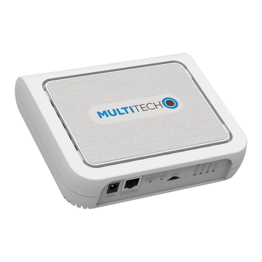
Connectors and LEDs

Note: Some features are available only on select models. The above image shows the model with all features.
| Item | Description |
| Connectors | |
| Power | 5 Volt power jack. |
| Ethernet | RJ45 Ethernet jack. |
| Reset | Reset button. Reboots the device or restores factory defaults. |
| WPS | Used by -002L models only. Wi-Fi pairing switch. |
| SIM | Available in -LEU1 and -LNA3 models only. SIM slot. |
| LEDs | |
| STATUS | Blinks when operating system is fully loaded. |
| LORA | Lights when LoRa software is active. |
| CELL | Used by -LEU1 and -LNA3 models only. Lights when there is power to the cellular radio. Blinks when the SIM is registered with the carrier. |
| WIFI | Used by -002 models only. Lights when there is a Wi-Fi connection. |
| Ethernet Link | Left LED on the Ethernet connector. Blinks when there is transmit and receive activity on the Ethernet link. It shows a steady light when there is a valid Ethernet connection. |
| Ethernet Speed | Right LED on the Ethernet connector. Lit when the Ethernet is linked at 100 Mbps. If it is not lit, the Ethernet is linked at 10 Mbps. |
Installing a SIM Card
If you have a cellular device with a SIM slot, you'll need a micro SIM card from your network provider. To install the SIM card:
- With the contact side facing down, align the notched edge as shown on the following image and slide the SIM card completely into the SIM holder.


Cabling Your Device
To cable the MTCAP:
- Connect the Ethernet cable to the Ethernet port on the device and to a PC.
- Connect the power supply to the power jack and wait 30 seconds for the device to power up.
Logging in to AEP
After connecting and powering up your device, login to AEP:
- Open an Internet browser. In the browser's address field, enter the device's default address for the device: 192.168.2.1. The login page appears.
- Type the default user name: admin.
- Type the default password: admin.
- Click Login to start the First Time Setup Wizard.
Setting a New Password
Note: For security reasons, we recommend you change the default password.
To set a new password:
- Click Next on the Welcome panel.
- In the Current Password field, enter the default password, admin.
- In the New Password field, enter a new password.
- Enter the new password in the Confirm Password field.
- Click Next.
Setting Time Zone, Time, and Date
To set the time zone, date, and time:
- Type today's Date in the format shown or use the calendar (data picker).
- Type the current Time (24-hour format).
- Select the Time Zone in which the device operates.
- Click Next.
Configuring PPP
Note: For models with cellular radios only.
To configure the Cellular PPP:
- To use PPP, check Enable. When enabled, your device functions as a cellular device.
- To enable dial-on-demand, check Dial-on-Demand. This tells the device to only make a PPP connection when there is outgoing IP traffic, and it brings the PPP connection down after a given idle timeout.
- The default Idle timeout is 180 seconds. If desired, you can enter a different value.
- Type the APN (Access Point Name). The APN is assigned by your wireless service provider.
- Click Next.
Setting Up PPP Authentication
To setup cellular PPP authentication:
- Select an authentication protocol Type used to negotiate with the remote peer: pap, chap, or pap-chap. The default is None.
- Type the Username for the remote peer to use for authentication. Optional. Username is limited to 60 characters.
- Type the Password for the remote peer to use for authentication. Optional. Password is limited to 60 characters.
- Click Next to exit the wizard.
Enter IP Address and Network Information
Set the IP address and network information for the Ethernet port:
Note: Leave the interface static unless using a DHCP server on the network that the device is connecting to. If you select DHCP client, you need to know which address is assigned to the Conduit. For information on DHCP settings, refer to DHCP in the AEP Help.
- Type the device's IP Address.
- Enter the network Mask.
- Enter the Gateway address (optional and not displayed when Cellular is enabled).
- Enter the Primary DNS server address (optional and not displayed when Cellular is enabled).
- Enter the Secondary DNS server address (optional and not displayed when Cellular is enabled).
- Click Next.
Configuring Access
When Cellular is disabled, the default settings enable HTTPRedirect to HTTPs via LAN.
Note: Enabling HTTPs via WAN can increase security risk including allowing web users to access the WAN interface.
- Under HTTPRedirect to HTTPs, check Enabled to turn on or uncheck to turn off.
- Enter Port or use default value.
- Check either Via LAN or Via WAN.
- Under HTTPs, enter Port or use default value.
- Click Finish.
Finishing Basic Configuration
When you finish entering basic settings:
- To save and apply the settings, click Save and Restart near the top of the left sidebar. The device restarts.
- After restart, log back into the AEP interface. On the Dashboard under Cellular, the PPP state displays Link is Up. You may have to wait for short time.
Getting Started LoRa
To get started with LoRa
- If you are not logged in to AEP, log in to the web management interface.
- Access LoRa Network Server Configuration by going to Setup > LoRa Network Server on the left sidebar.
- Modify the following settings as needed. For advanced settings, more detailed field descriptions, and information on configuring endpoints, go to
http://www.multitech.net/developer/software/lora/
| Field | MTAC-LORA-915 (NA) | MTAC-LORA-868 (EU) |
| Enabled | Checked | Checked |
| Frequency Band | 915 | 868 |
| Frequency Sub Band | 1 to 8 | NA |
| Additional Channels | NA | 863.5 – 867.5 MHz |
| 869.1 – 869.5 MHz | ||
| Name | LoRa network name (case sensitive) | |
| Passphrase | LoRa network security passphrase (case sensitive) | |
Additional Information
For additional information, including how to configure LoRa devices to communicate with the MTCAP, visit http://www.multitech.net.
- For help using LoRa, go to:
http://www.multitech.net/developer/software/lora/ - For help using AEP, go to
http://www.multitech.net/developer/software/aep/.
Mounting the MTCAP
The device ships with a mounting bracket. You will need:
- MTCAP with mounting bracket
- Screwdriver
- Drill
- Four #6 screws, with anchors (not provided)
Determining Location for the MTCAP
- Select a location that is central to all the devices you want to connect to this MTCAP. Place the device as high as possible, such as near the top of a wall.
- Avoid obstructions. Thick walls and reflective surfaces, such as metal, weaken the signal between the MTCAP and other devices.
- Note the location of the LoRa antenna in the following image. The signal will be strongest radiating from that side of the device. The LoRa antenna is 31.2 mm long.
- The LoRa antenna is an omni-directional antenna, but for best results, mount the device so the LoRa antenna is in a vertical position near the top of a wall. We recommend conducting a site survey to test the signal strength in different locations before you mount the device.
Mounting the MTCAP
- Determine where you want to mount the device.
- Mark where you want the screws to go.
- Drill holes for the screws and insert anchors.
- Place the mounting bracket and secure it with screws.
- Attach the device to the bracket and rotate to lock into place


Safety and Regulatory Content
For safety and regulatory content, refer to the MultiConnect Conduit Access Point Developer Guide, which is available at www.multitech.com.
MultiTech declares that this device is in compliance with the essential requirements and other relevant provisions of Directive 2014/53/EU. The declaration of conformity may be requested at https://support.multitech.com.
Copyright and Trademark
This publication may not be reproduced, in whole or in part, without the specific and express prior written permission signed by an executive officer of Multi-Tech Systems, Inc. All rights reserved. Copyright © 2017 by Multi-Tech Systems, Inc.
Multi-Tech Systems, Inc. makes no representations or warranties, whether express, implied or by estoppels, with respect to the content, information, material and recommendations herein and specifically disclaims any implied warranties of merchantability, fitness for any particular purpose and non-infringement.
MultiTech, MultiConnect, and the MultiTech logo are registered trademarks of Multi-Tech Systems, Inc. All other brand and product names are trademarks or registered trademarks of their respective companies.
Multi-Tech Systems, Inc
2205 Woodale Drive
Mounds View, Minnesota 55112 U.S.A
Phone: 763-785-3500 or 800-328-9717
Fax: 763-785-9874
Support
htttps://support.multitech.com
Europe, Middle East, Africa:
support@multitech.co.uk
+(44) 118 959 7774
U.S., Canada, all others:
support@multitech.com
(800) 972-2439 or (763) 717-5863

Documents / Resources
References
MultiTech Developer Resources » LoRa
MultiTech Developer Resources
MultiTech Developer Resources » mPower
![www.multitech.com]() MultiTech: IoT Devices & Hardware Company | IoT Device Management
MultiTech: IoT Devices & Hardware Company | IoT Device ManagementMultiTech Product Support Portal
Download manual
Here you can download full pdf version of manual, it may contain additional safety instructions, warranty information, FCC rules, etc.
Download Multitech MultiConnect ConduitTM Access Point Quick Start Guide
Advertisement


Need help?
Do you have a question about the MultiConnect Conduit MTCAP and is the answer not in the manual?
Questions and answers