Table of Contents
Troubleshooting

Subscribe to Our Youtube Channel
Related Manuals for Fluke 2640A


Summary of Contents for Fluke 2640A
- Page 1 2640A/2645A NetDAQ Data Acquisition Tools Service Manual PN 942615 March 1995 © 1995 Fluke Corporation, Inc. All rights reserved. Printed in U.S.A. ® All product names are trademarks of their respective companies.
- Page 2 Fluke authorized resellers shall extend this warranty on new and unused products to end-user customers only but have no authority to extend a greater or different warranty on behalf of Fluke. Warranty support is available if product is purchased through a Fluke authorized sales outlet or Buyer has paid the applicable international price.
- Page 3 SAFETY TERMS IN THIS MANUAL This instrument has been designed and tested in accordance with IEC publication 1010-1 (1992-1), Safety Requirements for Electrical Measuring, Control and Laboratory Equipment, and ANSI/ISA-582.01-1994, and CAN/CSA-C22.2 No. 1010.1-92. This User Manual contains information, warning, and cautions that must be followed to ensure safe operation and to maintain the instrument in a safe condition.
- Page 4 USE THE PROPER POWER CORD Use only the power cord and connector appropriate for the voltage and plug configuration in your country. Use only a power cord that is in good condition. Refer power cord and connector changes to qualified service personnel. DO NOT OPERATE IN EXPLOSIVE ATMOSPHERES To avoid explosion, do not operate the instrument in an atmosphere of explosive gas.
-
Page 5: Table Of Contents
2640A DC Voltage Measurement Specifications......1-13 1-22. 2640A AC Voltage Measurement Specifications......1-14 1-23. 2640A Four-Wire Resistance Measurement Specifications..1-16 1-24. 2640A Two-Wire Resistance Measurement Specifications ..1-16 1-25. 2640A Four-Wire RTD per ITS-1990 Measurement Specifications................1-17 1-26. 2640A Two-Wire RTD per ITS-1990 Measurement Specifications.......... - Page 6 NetDAQ Service Manual 1-34. 2645A Four-Wire RTD per ITS-1990 Measurement Specifications................. 1-24 1-35. 2645A Thermocouple per ITS-1990 Measurement Specifications................. 1-24 1-36. 2645A Frequency Measurement Specifications......1-26 Theory of Operation................2-1 2-1. Introduction .................... 2-5 2-2. Functional Block Description..............2-5 2-3.
- Page 7 Contents (continued) 2-75. A4 Analog Input PCA Circuit Description ........2-43 2-76. A1 Main to A3 A/D Converter Communications........2-44 2-77. Special Codes..................2-44 2-78. Resets ....................2-44 2-79. Commands..................2-45 2-80. Perform Scan ................. 2-45 2-81. Perform Self-Test................2-46 2-82.
- Page 8 Four-Terminal Resistance Accuracy Test (2640A)....... 4-15 4-17. Four-Terminal Resistance Accuracy Test (2645A)....... 4-17 4-18. RTD Temperature Accuracy Test (Resistance) (2640A) ....4-18 4-19. RTD Temperature Accuracy Test (Resistance) (2645A) ....4-19 4-20. RTD Temperature Accuracy Test (DIN/IEC 751 RTD) ....4-19 4-21.
- Page 9 Contents (continued) 4-37. VDC Calibration Procedure............4-31 4-38. VAC Calibration Procedure............4-32 4-39. Resistance Calibration Procedure..........4-33 4-40. Frequency Calibration Procedure ..........4-34 4-41. Calibration Procedure (Manual) ............4-34 4-42. Manual Calibration Commands............. 4-36 4-43. Manual VDC Calibration Procedure ..........4-37 4-44.
- Page 10 NetDAQ Service Manual List of Replaceable Parts ..............6-1 6-1. Introduction .................... 6-3 6-2. How To Obtain Parts................6-3 6-3. Manual Status Information..............6-3 6-4. Newer Instruments.................. 6-4 6-5. Service Centers..................6-4 Schematic Diagrams................7-1...
- Page 11 1-12. 2640A/2645A Real-Time Clock and Calendar ........1-12 1-13. 2640A DC Voltage General Specifications ........... 1-13 1-14. 2640A DC Voltage Range and Resolution Specifications..... 1-13 1-15. 2640A DC Voltage Accuracy Specifications......... 1-14 1-16. 2640A AC Voltage General Specifications ........... 1-14 1-17.
- Page 12 NetDAQ Service Manual 1-36. 2645A Four-Wire Resistance Accuracy Specifications ......1-23 1-37. 2645A Four-Wire RTD Temperature Coefficient........1-24 1-38. 2645A Four-Wire RTD Specifications ..........1-24 1-39. 2645A Thermocouple General Specifications ........1-24 1-40. 2645A Thermocouple Specifications ............. 1-25 1-41. 2645A Frequency Accuracy Specifications ........... 1-26 1-42.
- Page 13 2640A/2645A Final Assembly............... 6-5 6-2. A1 Main PCA Assembly ................ 6-10 6-3. A2 Display PCA Assembly ..............6-15 6-4. 2640A A3 A/D Converter PCA Assembly..........6-17 6-5. 2645A A3 A/D Converter PCA Assembly..........6-22 6-6. A4 Analog Input PCA Assembly ............6-27...
- Page 14 NetDAQ Service Manual...
- Page 15 List of Figures Figure Title Page 1-1. 2640A/2645A NetDAQ Networked Data Acquisition Units ....1-3 2-1. Interconnection Diagram................ 2-5 2-2. Overall Functional Block Diagram ............2-6 2-3. Power Supply Block Diagram ..............2-7 2-4. Command Byte Transfer Waveforms............. 2-29 2-5.
- Page 16 NetDAQ Service Manual 6-2. A1 Power Supply PCA................6-14 6-3. A2 Display PCA Assembly ..............6-16 6-4. 2640A A3 A/D Converter PCA Assembly..........6-21 6-5. 2645A A3 A/D Converter PCA Assembly..........6-26 6-6. A4 Analog Input PCA Assembly ............6-28...
- Page 17 1-16. Trigger Out ................1-11 1-17. Master Alarm................1-11 1-18. 2640A/2645A Totalizer..............1-12 1-19. 2640A/2645A Real-Time Clock and Calendar ......1-12 1-20. 2640A Specifications ................ 1-13 1-21. 2640A DC Voltage Measurement Specifications ......1-13 1-22. 2640A AC Voltage Measurement Specifications ......1-14 1-23.
- Page 18 NetDAQ Service Manual 1-29. 2645A Specifications ................ 1-20 1-30. 2645A DC Voltage Measurement Specifications ......1-20 1-31. 2645A AC Voltage Measurement Specifications ......1-21 1-32. 2645A Four-Wire Resistance Measurement Specifications..1-23 1-33. 2645A Two-Wire Resistance Measurement Specifications..1-23 1-34. 2645A Four-Wire RTD per ITS-1990 Measurement Specifications ................
-
Page 19: Introduction And Specification
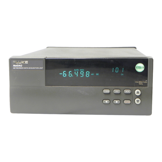
NetDAQ Logger for Windows application to provide an operating environment for the instruments, including testing and calibration. The 2640A and 2645A networked data acquisition units are identical in operation and appearance, and vary only in emphasis: The 2640A emphasizes precision and supports up to 100 measurements per second, with 5 ½... - Page 20 [1] The 300V value is for channels 1 and 11 only; the 150V value is for all other channels. [2] Drift Correction refers to an automatic internal measurement step performed with each scan to correct for drift due to changes in ambient temperature and humidity. Table 1-2. Summary of 2640A/2645A Measurement Capabilities Capability 2640A...
- Page 21 Introduction and Specification Introduction Table 1-2. Summary of 2640A/2645A Measurement Capabilities (cont) Capability 2640A 2645A Temperature Measurements Thermocouples: Thermocouples: (Thermocouple) [2] K R S E K R S E T B C N T B C N Temperature Measurements RTD R0: 10 to 1010...
-
Page 22: Options And Accessories
Table 1-4 summarizes the available models, options and accessories, including measurement transducers, software, connector sets, Ethernet interfaces, cables, and components. Table 1-4. Models, Options and Accessories Model Description 2640A NetDAQ Instrument 2645A NetDAQ Instrument NetDAQ Logger for Windows (Isolated Network) 264XA-901... -
Page 23: Operating Instructions
1-7. This manual focuses on performance tests, calibration procedures, and component-level repair of the 2640A and 2645A networked data acquisition units. To that end, manual chapters are often interdependent; effective troubleshooting may require not only reference to the troubleshooting procedures in Chapter 5, but also some understanding of the detailed Theory of Operation in Chapter 2 and some tracing of circuit operation in the Schematic Diagrams presented in Chapter 7. -
Page 24: Conventions
1-9. Specifications are divided into three sections. The first section contains the combined specifications that apply equally to both the 2640A and 2645A instruments. The second section contains specifications that apply only to the 2640A instrument. The third section contains specifications that apply only to the 2645A instrument. -
Page 25: 2640A/2645A General Specifications
Introduction and Specification Specifications 2640A/2645A General Specifications 1-11. Table 1-5 provides the general specifications for the 2640A and 2645A instruments. Table 1-5. 2640A/2645A General Specifications Specification Characteristic Channel Capacity I/O Lines Total Size 9.3 cm (3.67 in) high, 21.6 cm (8.5 in) wide, 36.2 cm (14.28 in) deep Weight Net, 4 kg (8.8 lb.) Shipping, 6.0 kg (13.2 lb.) -
Page 26: 2640A/2645A Environmental Specifications
NetDAQ Service Manual 2640A/2645A Environmental Specifications 1-12. Table 1-6 provides a summary of the environmental specifications for the 2640A/2645A. Table 1-6. Environmental Specifications Specification Characteristic Warmup Time 1 hour to rated specifications -or- 15 minutes if relative humidity (noncondensing) is 50% or less. - Page 27 1-15. Table 1-8 provides a summary of the Trigger In specifications. The Trigger In input is located on the ALARM/TRIGGER I/O connector, terminals TI and GND. Table 1-8. 2640A/2645A Trigger In (TI) Specification Specification Characteristic Logical High - Trigger not set Minimum: 2.0V...
-
Page 28: 2640A/2645A Totalizer
Maximum Count 4,294,967,295 2640A/2645A Real-Time Clock and Calendar 1-19. Table 1-12 provides a summary of the battery powered real-time clock and calendar. Table 1-12. 2640A/2645A Real-Time Clock and Calendar Specification Characteristic Accuracy 1 minute per month for 0°C to 50°C range Battery Life >15 unpowered instrument years for 0°C to 28°C (32°F to 82.4°F). -
Page 29: 2640A Specifications
This section includes specifications specific to the 2640A instrument by measurement function. 2640A DC Voltage Measurement Specifications 1-21. Tables 1-13 to 1-15 provide 2640A specifications for the dc voltage measurement function. Table 1-13. 2640A DC Voltage General Specifications Specification Characteristic Input Impedance 100 MΩ... -
Page 30: 2640A Ac Voltage Measurement Specifications
The 750 mV range is used internally to the instrument and not user selectable. ** 300V range applies to channels 1 and 11 only. 2640A AC Voltage Measurement Specifications 1-22. Tables 1-16 to 1-18 provide 2640A specifications for the ac voltage measurement function. Table 1-16. 2640A AC Voltage General Specifications Specification... - Page 31 Introduction and Specification Specifications Table 1-17. 2640A AC Voltage Range and Resolution Specifications Resolution Range Minimum Input for Rate Accuracy Slow Fast Full Scale +30,000 +3,000 10 µV 100 µV 300 mV 20 mV 100 µV 1 mV 200 mV...
-
Page 32: 2640A Four-Wire Resistance Measurement Specifications
2640A Two-Wire Resistance Measurement Specifications 1-24. The 2640A specifications for the two-wire resistance measurement function is based on the four-wire resistance measurement specification (above) except you add a nominal 5-ohm (10-ohm maximum) positive offset. This value varies for each channel and with temperature (nominal +1%/ºC). -
Page 33: 2640A Four-Wire Rtd Per Its-1990 Measurement Specifications
Specifications 2640A Four-Wire RTD per ITS-1990 Measurement Specifications 1-25. Tables 1-22 and 1-23 provide 2640A specifications for the four-wire Resistance- Temperature Detector (RTD) measurement function. The four-wire measurements use 2 input channels a decade apart, e.g., channels 4 and 14. -
Page 34: 2640A Thermocouple Per Its-1990 Measurement Specifications
NetDAQ Service Manual 2640A Thermocouple per ITS-1990 Measurement Specifications 1-27. Tables 1-24 to 1-25 provide 2640A specifications for the thermocouple measurement function per ITS-1990. Table 1-24. 2640A Thermocouple General Specifications Specification Characteristic Input Impedance 100 MΩ minimum in parallel with 300 pF... -
Page 35: 2640A Frequency Measurement Specifications
2.10 3.20 3.40 4.60 2640A Frequency Measurement Specifications 1-28. Tables 1-26 to 1-27 provide 2640A specifications for the frequency measurement function. Table 1-26. 2640A Frequency Accuracy Specifications Frequency Measurement Accuracy, 1 Year, -10°C to 60°C Range Resolution Accuracy + (% input + Hz) -
Page 36: 2645A Specifications
NetDAQ Service Manual Table 1-27. 2640A Frequency Sensitivity Specifications Frequency Measurement Sensitivity (Sinewave) Frequency Range Minimum Signal Maximum Signal 15 Hz to 70 kHz 100 mV ac rms V<150/300Vrms [1] and Vx Hz<2x10 70 kHz to 100 kHz 100 mV ac rms... -
Page 37: 2645A Ac Voltage Measurement Specifications
Introduction and Specification Specifications Table 1-29. 2645A DC Voltage Resolution and Repeatability Specifications Resolution Range Slow Fast 3 µV 6 µV 90 mV 1 µV 3 µV 300 mV 10 µV 30 µV 100 µV 300 µV 1 mV 3 mV Table 1-30. - Page 38 NetDAQ Service Manual Table 1-32. 2645A AC Voltage Range and Resolution Specifications Resolution Range Minimum Input for Rate Accuracy Slow Fast Full Scale +30,000 +3,000 10 µV 100 µV 300 mV 20 mV 100 µV 1 mV 200 mV 1 mV 10 mV Table 1-33.
-
Page 39: 2645A Four-Wire Resistance Measurement Specifications
Introduction and Specification Specifications 2645A Four-Wire Resistance Measurement Specifications 1-32. Tables 1-34 to 1-36 provide 2645A specifications for the four-wire resistance measurement function. The four-wire measurements use 2 input channels a decade apart, e.g., channels 4 and 14. Table 1-34. 2645A Four-Wire Resistance Temperature Coefficient Specification Characteristic Add 1/10th the 90 day specification per °C above 28°C or below 18°C. -
Page 40: 2645A Four-Wire Rtd Per Its-1990 Measurement Specifications
NetDAQ Service Manual 2645A Four-Wire RTD per ITS-1990 Measurement Specifications 1-34. Tables 1-37 and 1-38 provide 2645A specifications for the four-wire Resistance- Temperature Detector (RTD) measurement function. The four-wire measurements use 2 input channels a decade apart, e.g., channels 4 and 14. There is no two-wire RTD capability for the 2645A. - Page 41 Introduction and Specification Specifications Table 1-40. 2645A Thermocouple Specifications Accuracy + °C 18°C to 28°C -10°C to 60°C Thermocouple Resolution 90 Day 1 Year 1 Year Temperature °C Type Slow Slow Fast Slow Fast -100 to 80 80 to 230 230 to 760 -100 to -25 -25 to 120...
-
Page 42: 2645A Frequency Measurement Specifications
NetDAQ Service Manual 2645A Frequency Measurement Specifications 1-36. Tables 1-41 to 1-42 provide 2645A specifications for the frequency measurement function. Table 1-41. 2645A Frequency Accuracy Specifications Frequency Measurement Accuracy, 1 Year, -10°C to 60°C Range Resolution Accuracy + (% input + Hz) Slow Fast Slow... -
Page 43: Theory Of Operation
Chapter 2 Theory of Operation Title Page 2-1. Introduction .................... 2-5 2-2. Functional Block Description..............2-5 2-3. A1 Main PCA Block Description ............2-7 2-4. Power Supply................2-7 2-5. Digital Kernel ................2-7 2-6. Serial Communication (Guard Crossing) ........2-8 2-7. - Page 44 NetDAQ Service Manual 2-31. Digital Kernel ................2-13 2-32. Reset Circuits................2-14 2-33. Microprocessor ................. 2-14 2-34. Address Decoding..............2-16 2-35. Flash Memory................2-18 2-36. Static RAM ................2-18 2-37. Real-Time Clock............... 2-19 2-38. FPGA (Field Programmable Gate Array)......... 2-19 2-39.
- Page 45 Theory of Operation Introduction 2-79. Commands ..................2-45 2-80. Perform Scan ................2-45 2-81. Perform Self-Test ................. 2-46 2-82. Return Main Firmware Version............ 2-46 2-83. Return Boot Firmware Version ............ 2-47 2-84. Set Global Configuration.............. 2-47 2-85. Set Channel Configuration ............2-47 2-86.
- Page 46 NetDAQ Service Manual...
-
Page 47: Introduction
Theory of Operation Introduction Introduction 2-1. The theory of operation begins with a general overview of the instrument and progresses to a detailed description of the circuits of each pca. The instrument is first described in general terms with a Functional Block Description. Then, each block is detailed further with Detailed Circuit Descriptions. - Page 48 NetDAQ Service Manual Terminal Strips Input Multiplexing Reference Junction A4 Analog Input Input Protection Input Signal Conditioning Analog Measurement Processor A/D Converter EPLD Microprocessor, RAM, and Flash A3 A/D Converter Inguard Serial Guard Crossing Outguard Communications RS-232 µP RAM and Flash Real-Time Memory...
-
Page 49: A1 Main Pca Block Description
Theory of Operation Functional Block Description A1 Main PCA Block Description 2-3. The A1 Main pca description is divided into sections for each primary pca function as described below. Power Supply 2-4. The Power Supply functional block (Figure 2-3) provides voltages required by the outguard digital circuitry: +4.9V dc (Vcc);... -
Page 50: Serial Communication (Guard Crossing)
NetDAQ Service Manual • Communicates with the microprocessor on the A/D Converter PCA via the Serial Communication (Guard Crossing) block (A1U5, A1U7). • Communicates with the Display Controller to display readings and user interface information (A1U1, A1U31). • Communicates with the Field Programmable Gate Array (A1U31), which scans the user interface keyboard found on the Display Assembly and interfaces with the Digital I/O hardware. -
Page 51: Analog Measurement Processor
This circuitry consists of a set of relays and relay-control drivers. The relays form a tree that routes the input channels to the measurement circuitry. Two of the relays are also used to switch between two-wire and four-wire operation. For signal switching and selection, the 2640A uses reed relays, while the 2645A uses solid-state relays. -
Page 52: Open Thermocouple Check
NetDAQ Service Manual Open Thermocouple Check 2-17. Under control of the Inguard Microprocessor, the open thermocouple check circuit applies a small ac signal to a thermocouple input before each measurement. If an excessive resistance is encountered, an open thermocouple input condition is reported. A4 Analog Input PCA Block Description 2-18. -
Page 53: Raw Dc Supply
Theory of Operation Detailed Circuit Description Raw DC Supply 2-24. The raw dc supply circuitry receives input from power transformer T401, which operates from an ac source of 107V to 264V ac. The power transformer is energized whenever the power cord is plugged into the ac line; there is no on/off switch on the primary side of the transformer. -
Page 54: Inverter
NetDAQ Service Manual The pulse-width modulator comparator in A1U9 compares the output to an internal reference and sets the ON-time/OFF-time ratio to regulate the output to 4.9V dc. A1C1 is the input filter capacitor, and A1C14 and A1C18 are the output filter capacitors. Proper inductor and capacitor values set the filter frequency response to ensure best overall system stability. -
Page 55: Digital Kernel
Theory of Operation Detailed Circuit Description Inverter Inguard Supply 2-29. The inverter inguard supply provides three outputs: +5.2V dc (Vdd) and -5.2V dc (Vss) for the inguard analog and digital circuitry, and +5.6V dc (Vddr) for the relays. Diodes A1CR5 and A1CR6, and capacitor A1C12 create a +6.8V dc source, while diodes A1CR7 and capacitor A1C13 create a -9.5V dc source. -
Page 56: Reset Circuits
NetDAQ Service Manual Reset Circuits 2-32. The Power-On Reset signal (POR*, A1U10-7) is generated by the Microprocessor Supervisor, which monitors the voltage of Vcc at A1U10-2. If Vcc is less than +4.65 volts, then A1U10-7 is driven low. POR* drives the enable inputs of the four tri-state buffers in A1U2, causing the HALT*, RESET*, and DRST* signals to be driven low when POR* is low. - Page 57 Theory of Operation Detailed Circuit Description One sixteen-bit timer in the Microprocessor is used to keep track of the time to the nearest millisecond. The timer counter runs off the 15.36 MHz clock at a rate of 1/64th millisecond. The CINT* signal from the Real Time Clock chip (A1U11) causes the timer counter to be sampled every 1/64th of a second.
-
Page 58: Address Decoding
NetDAQ Service Manual Table 2-1. Microprocessor Interrupt Sources Microprocessor Pin Signal Name Description A1U1-96 CINT* Real-Time Clock Interrupt; 64 per second. A1U1-121 XTINT* External Trigger Interrupt. A1U1-120 KINT* Keyboard Interrupt; interrupts on each debounced change of keyboard conditions. A/D Communication Interrupt; internal to the microprocessor. - Page 59 Theory of Operation Detailed Circuit Description The RAM* signal (A1U1-127) enables access to the Static RAM (A1U20, A1U30, A1U34, or A1U35). There are two banks of static RAM. The SRAM decoding circuit (A1U14, A1U15, A1R125, and A1R126) selects one of the two banks. The RAM1* signal selects one bank (A1U20 and A1U30) and RAM2* selects the other bank (A1U34 and A1U35).
-
Page 60: Flash Memory
NetDAQ Service Manual Flash Memory 2-35. The Flash EPROM is an electrically erasable and programmable memory that provides storage of instructions for the Microprocessor and measurement calibration data. A switching power supply composed of A1U12, A1L3, A1CR16, A1C11, A1C15, A1C86, and A1C97 generates a nominal +12 volt programming power supply (Vpp) when the Microprocessor drives VPPEN high (A1U12-2). -
Page 61: Real-Time Clock
Theory of Operation Detailed Circuit Description Real-Time Clock 2-37. The Real-Time Clock maintains time and calendar date information for use by the instrument. A nonvolatile power supply (Vbb) biases A1U11. The Microprocessor Supervisor (A1U10) monitors the voltage on Vcc (A1U10-2). If Vcc is greater than the voltage of the lithium battery (A1U10-8), A1U10 switches Vcc from A1U10-2 to A1U10-1 (Vbb). - Page 62 NetDAQ Service Manual The FPGA contains the following eight functional elements after the Microprocessor has loaded the configuration into the FPGA: • Clock Dividers • Internal Register Address Decoding • Keyboard Scanner • Digital I/O Buffers • Latches • Totalizer Debouncing and Mode Selection •...
-
Page 63: Serial Communication (Guard Crossing)
Theory of Operation Detailed Circuit Description Totalizer Debouncing and Mode Selection Logic internal to the FPGA lets the Microprocessor enable a debouncer in the Totalizer input signal path. You can find the detailed description of the Totalizer Debouncer and Mode Selection later in this chapter under the heading "Totalizer Input."... -
Page 64: Ethernet Interface
NetDAQ Service Manual Data Terminal Ready (DTR) and Request To Send (RTS) are modem control signals controlled by the Microprocessor. When the instrument is powered up, the Microprocessor initially sets DTR and RTS false by setting A1U1-61 and A1U1-59 high, which results in the RS-232 driver outputs (A1U13-7 and A1U13-5 respectively) going to -5.0V dc. - Page 65 Theory of Operation Detailed Circuit Description The clock for the Ethernet Chip is provided by A1Y2, A1C38, and A1C89, which are connected directly to A1U32-17 and A1U32-18. This provides a 20 MHz clock to the Ethernet Chip. The clock allows the Ethernet Interface to send and receive data at 10 M-bits per second.
-
Page 66: Digital Inputs And Outputs
NetDAQ Service Manual Pulse transformer A1T3 provides electrical isolation between the Ethernet Chip (A1U32) and the 10BASE-2 transceiver chip (A1U16). Data is transmitted from the Ethernet Chip (A1U32) to the transceiver chip (A1U16) through pins 1, 2, 15, and 16 of pulse transformer A1T3. -
Page 67: Digital And Alarm Output Drivers
Theory of Operation Detailed Circuit Description Digital and Alarm Output Drivers 2-45. Since the 11 Digital Output and Alarm Output Drivers are identical in design, the following example description references only the components that are used for the Master Alarm Output (AO<2>). The Microprocessor controls the state of the Master Alarm Output Driver by writing to the Alarm Output register in the FPGA (A1U31) to set the level of output A1U31-61. -
Page 68: A2 Display Pca Circuit Description
NetDAQ Service Manual The input (XTI) is then routed to the FPGA (A1U31), that contains the External Trigger control circuitry. The Microprocessor sets control register bits in the FPGA (A1U31) to control the external trigger circuit. The External Trigger control circuit output (A1U31-9) drives an interrupt input on the Microprocessor (A1U1-121). -
Page 69: Front Panel Switches
Theory of Operation Detailed Circuit Description Table 2-4. A2 Display Power Supply Connections Power Supply A2J1 Pins Nominal Voltage +4.9V dc -5.0V dc Vload -30V dc FIL1/FIL2 5.4V ac Front Panel Switches 2-50. The FPGA monitors the front panel switches (see below) using six interface signals SWR1 through SWR6. -
Page 70: Display
NetDAQ Service Manual Table 2-5. Front Panel Switch Scanning Interface Signal States or Key Sensed Step SWR6 SWR5 SWR4 SWR3 SWR2 SWR1 A2S17 A2S10 A2S12 A2S18 A2S13 A2S11 A2S14 A2S15 A2S16 A2S21 A2Sn indicates switch closure sensed. 0 indicates strobe driven to logic 0. Z indicates high impedance input state ignored. -
Page 71: Watchdog Timer And Reset Circuit
Theory of Operation Detailed Circuit Description Watchdog Timer and Reset Circuit 2-53. The Watchdog Timer and Reset circuit has been defeated by the insertion of the jumper between TP1 and TP3 on the Display Assembly. In this instrument, the reset circuitry is on the Main Assembly and the Watchdog Timer is part of the Microprocessor (A1U1). - Page 72 NetDAQ Service Manual Table 2-6 defines the logic and the selection process for the four display initialization modes. Table 2-6. Display Initialization Modes A2TP4 A2TP5 Power-Up DTEST* LTE* Display Initialization All Segments OFF All Segments ON (default) Display Test Pattern #1 Display Test Pattern #2 The two display test patterns are a mixture of on and off segments forming a recognizable pattern that allows for simple testing of display operation.
-
Page 73: A3 A/D Converter Pca Circuit Description
• Muli-Slope A/D converter comprised of discrete components and an FPGA (Field Programmable Gate Array) (U18). The difference between the A/D boards is that the 2640A uses reed relays, while the 2645A uses optically coupled solid state relays. 2-31... - Page 74 NetDAQ Service Manual A4 Analog Input EMI Filters Ch11 to 20 Ch1 to 10 Scanner Relays Scanner Relays Relay Drivers Treeing Relays Ohms Current Source Voltage Input Input Protection Signal Conditioning Selectable Gains DC Buffer Amplifier x4.021 x32.168 +3.45V dc A/D Converter FPGA References...
-
Page 75: Stallion Chip
• Active filtering of ac voltage measurements The Stallion IC design is based on the Mercury A/D Chip used in Fluke 45 and Hydra, except it does not contain the A/D conversion function, that is now done using discrete components using a multi-slope technique. -
Page 76: Channel Selection Circuitry
Channel Selection Circuitry 2-60. Channel selection is done using reed relays on the 2640A and by optically coupled solid-state relay on the 2645A. Channel selection is done by a set of 24 relays organized in a tree structure. Relays A3K1 through K20 select the specific channel 1-20. The... - Page 77 Theory of Operation Detailed Circuit Description Table 2-8. Measurement Matrix for DC Volts DC Volt Input to Full-Scale Gain of DC Full-Scale DC Buffer Range Range Stallion Output of Buffer Amplifier Volts Input to Control Signal Stallion Multislope A/D 90 mV Direct 90 mV 32.168...
-
Page 78: Ohms And Rtd Measurement Circuitry
NetDAQ Service Manual Ohms and RTD Measurement Circuitry 2-62. Resistance measurements are made by sourcing dc current through the unknown resistor and measuring the resultant dc voltage (see Table 2-9). The current source consists of operational amplifier A1U31, FET A3Q19, and switches internal to the Stallion. four-wire measurements use separate source and sense signal paths to the point of the unknown resistance. -
Page 79: Ac Volts Measurement Circuitry
Theory of Operation Detailed Circuit Description AC Volts Measurement Circuitry 2-63. AC-coupled voltage inputs are scaled by an ac buffer (A3U29), converted to dc by a true rms ac-to-dc converter (A3U26), filtered by an active ac volt filter, then sent to the Stallion IC, the Buffer Amplifier, and the A/D Conversion Circuitry (see Table 2-10). -
Page 80: Voltage Reference Circuit
NetDAQ Service Manual Voltage Reference Circuit 2-66. The voltage reference circuit creates a well-regulated +3.45/-3.45V dc source for use by the A/D converter, and as a source for ohms and current measurements. The circuit is formed around two dual op-amps A3U12 and A3U20. A3U12 controls balance between +3.45V dc and -3.45V dc by adjusting the +3.45V dc through A3Q2 as the divider between these voltages in zener diode A3Z1 reads above or below zero. -
Page 81: Analog/Digital Converter Circuit
Theory of Operation Detailed Circuit Description A3U20 is also a dual op-amp. One half provides the regulated 3 mA required to flow into the cathode of the zener diode within A3Q5 by forming a current source with A3Q4. If not supplied from a current source, the current would change with the emitter base voltage of A3Q5. -
Page 82: Integrate
NetDAQ Service Manual Integrate 2-69. The integrate state is when the input voltage is actually connected to the integrator. PREF and NREF are each switched off and on 10 to 20 times during this state and DREF is still off, INT is on, AZ is off, and the CMP signal is switching off and on. The primary signal is pin 7 of A3U19, which looks approximately like a triangular wave with 51.2 µs slope when the input voltage is zero. - Page 83 Theory of Operation Detailed Circuit Description 0.5V/Div. 0V dc 125 µs/Div. Figure 2-12. Integrator Output Waveform for Input Near + Full Scale 0v dc 0.5V/Div. 125 µs/Div. Figure 2-13. Integrator Output Waveform for Input Near - Full Scale 2-41...
-
Page 84: Inguard Digital Kernel Circuitry
NetDAQ Service Manual Deintegrate1 2-70. Deintegrate1 is when the remaining charge of the capacitor is removed and the major count is completed. The input is turned off and no longer affects the reading. INT is off, PREF, and NREF continue to switch a few more times, and the signal is brought very close to zero. -
Page 85: Open Thermocouple Detect Circuitry
Theory of Operation Detailed Circuit Description Communication with the main processor is done using the IGDR line to receive and the IGDS line to send serial data. On the A/D side, these signals are called RECV DATA and XMIT DATA (pins A3U5-53 and A3U5-54 respectively). The RESET* signal is asserted on power-up for reset and during operation when a break signal is received from A1U4. -
Page 86: A1 Main To A3 A/D Converter Communications
NetDAQ Service Manual Temperature sensor transistor A4Q1 outputs a voltage inversely proportional to the temperature of the input channel terminals. This voltage is 0.6V dc at 25 °C, increasing 2 mV with each degree decrease in temperature, or decreasing 2 mV with each degree increase in temperature. -
Page 87: Commands
Theory of Operation A1 Main to A3 A/D Converter Communications Commands 2-79. A command consists of a six-byte packet sent from the outguard to the inguard. The most-significant four bits of the first bytes define the following command types: • Perform Scan. -
Page 88: Perform Self-Test
“F” for FFE (2645A) software and “P” for the PFE (2640A); xx are the two digits of the major version number, and yy are the two digits of the minor version number (there is an implicit decimal point between the two). -
Page 89: Return Boot Firmware Version
Range 90 mV or 300 ohm, 300 mV or 3 kΩ, 3V or 30 kohm, 30V or 300 kΩ, 50V (2645A), 150/300V (2640A), or 3 MΩ, 750 mV (reference junction calibration). The range field is ignored for frequency and thermocouple channels. -
Page 90: Do Housekeeping
NetDAQ Service Manual Do Housekeeping 2-86. The Command Packet tells the A/D to do the following: • Do all housekeeping readings if bit set. • Do the next housekeeping reading in the schedule if bit set. • Prescan: preset the function relays. Checksum Action Performed is as follows: •... -
Page 91: Power-Up Protocol
The channel multiplexing consists of treeing and channel switches, implemented with either FET switches (2645A) or reed relays (2640A). There are two sets of bits associated with these switches. The tree bits must be set to indicate which bank of channels is being used where bank 0 is channels 1 to 10, and bank 1 is channels 11-20. - Page 92 The tree bits should not be deselected, since this would result in excessive wear of these switches (for the 2640A). Table 2-12: Tree Bits gives the bit patterns for the tree bits and Table 2-13: Channel Bits gives the bit patterns for the channel bits.
-
Page 93: Function Relays
Stallion Chip and Signal Conditioning 2-95. The Stallion Chip (A3U30) is a Fluke-custom IC that contains assorted switches, amplifiers, and the frequency counter. The chip contains registers that the A3U5 A/D microprocessor may read and write to configure the chip and obtain frequency readings. - Page 94 NetDAQ Service Manual Table 2-17. Stallion Switch Settings Stallion Settings Function S Switches Other Switches VDC 90 mV 17 23 35 37 39 44 50 64 ACR4 FPWR RPCTL VDC 300 mV 17 23 35 37 39 44 50 64 ACR4 FPWR RPCTL...
-
Page 95: A/D
Theory of Operation Inguard Software Description After the input channel has been selected and the Stallion chip programmed appropriately, there is a minimum time required for the signal conditioning circuitry to settle. This settling time varies depending on the function and range being measured, and is given in Table 2-18: Signal Conditioning Settling Time. -
Page 96: Timing
Service Manual Timing 2-97. The timing for the 2645A and 2640A A/Ds is shown in Figures 2-14 and 2-15. These figures apply to normal readings. For Reference Balance readings, the timing for both 2645A and 2640A is given by Figure 2-15. - Page 97 Theory of Operation Inguard Software Description The A/D state machine has several modes of operation: perform conversion (measure input); do a reference balance reading with both references on; or do a reference balance reading with both references off. These modes are selected by the A3U5 A/D microprocessor through a two-bit parallel port, which consists of two data lines and a strobe line.
-
Page 98: Counters
K = (0.1)(2)(3.45) / (16) / (307) / (1.6) (2645A) K = (0.1)(2)(3.45) / (16) / (1843) / (1.6) (2640A) For higher resolution measurements, P and N counts are accumulated for the total number of A/D readings in the measurement and then used in the above formula. We call these Ptot and Ntot. -
Page 99: Discharge Signal
Theory of Operation Inguard Software Description We also must subtract the correct zero offset from the measurement. There are four zero offsets, one for each DC buffer amplifier gain setting (BR1, BR2, BR3, or BR4). The gain setting used for a particular function and range can be determined from the Stallion switch settings (Table 2-17: Stallion Switch Settings). -
Page 100: Measurement Types
They also do not apply to reference balance readings (see Reference Balance Readings). Table 2-20. A/D Readings to Average to Obtain a Measurement Instrument Reading Rate Fast Reading Rate Medium Reading Rate Slow 2640A 5 (60 Hz) 45 (60 Hz) 6 (50 Hz) 48 (50 Hz) 2645A 20 (60 Hz) -
Page 101: Thermocouples
Theory of Operation Inguard Software Description For the channels within such a block, we can assume the following: • No function relay switches are required. • There is only one Stallion register, that must be written to between channels. • A channel can be selected at the beginning of the deintegrate period of the previous channel, at the same time that the previous channel is deselected. -
Page 102: Autoranging
ACR1 (300 mV) Between 3V and 30V ACR2 (3V) Greater than 30V (2640A only) ACR3 (30V) The frequency measurement itself does not use the A/D. Frequency measurements are taken using the Stallion chip. To reduce noise in frequency measurements, the instrument takes eight frequency readings and averages them together to obtain a single frequency measurement. -
Page 103: Overload
2-22. Table 2-22. A/D Readings to Average to Obtain a Reference Balance Measurement Instrument Reading Rate Fast Reading Rate Medium Reading Rate Slow 2640A 5 (60 Hz) 45 (60 Hz) 6 (50 Hz) 48 (50 Hz) 2645A 5 (60 Hz) -
Page 104: Housekeeping Schedule
NetDAQ Service Manual The scale factor is derived as follows: S = 1 - {[(16P2 - N2) - (16P0 - N0)]K2} where S = scale factor P2 = P counts (both references on) N2 = N counts (both references on) P0 = P counts (both references off) N0 = N counts (both references off) K2 = (0.1) / (16) / (1843) / (1.6) -
Page 105: Self-Test Command
This test simply triggers the A/D and waits for either the A/D interrupt or a timeout. If the timeout occurs before receiving an A/D interrupt, the test fails and the A/D is assumed to be non-functional. The timeout is set to 10 ms, greater than either the 2640A or 2645A A/D reading time. - Page 106 NetDAQ Service Manual 2-64...
-
Page 107: General Maintenance
Chapter 3 General Maintenance Title Page 3-1. Introduction .................... 3-3 3-2. Warranty Repairs and Shipping ............. 3-3 3-3. General Maintenance................3-3 3-4. Required Equipment ................3-3 3-5. Power Requirements ................3-3 3-6. Static-Safe Handling ................3-3 3-7. Servicing Surface-Mount Assemblies ..........3-4 3-8. - Page 108 NetDAQ Service Manual...
-
Page 109: Introduction
Equipment required for calibration, troubleshooting, and repair of the instrument is listed in Chapter 4, Table 4-1. Refer to the Fluke "Surface-Mount Device Soldering Kit" for a list of special tools required to perform circuit assembly repair. (In the USA, call 1-800-526-4731 to order this kit.) -
Page 110: Servicing Surface-Mount Assemblies
Unique servicing, troubleshooting, and repair techniques are required to support this technology. Refer to Chapter 5 for additional information. Also, refer to the Fluke "Surface-Mount Device Soldering Kit" for a complete discussion of these techniques (in the USA, call 1-800-526-4731 to order this kit). -
Page 111: Replacing The Line Fuse
General Maintenance Line Fuse Replacing the Line Fuse 3-9. The line fuse (15/100 ampere, 250V, time delay, PN 944629) is in series with the power supply and located inside the instrument. To replace the fuse, refer to Figure 3-1 and the following procedure: WARNING Do not operate the instrument without the cover properly... - Page 112 NetDAQ Service Manual Remove Cables Bottom Remove Bottom Screws (4 places) Remove Rear Bezel Screws (2 places) Remove Rear Bezel Case for Fuse Fuse (15/100, 250V Access Time Delay) Figure 3-1. Replacing the Fuse...
-
Page 113: Disassembly Procedures
General Maintenance Disassembly Procedures Disassembly Procedures 3-10. The following paragraphs describe disassembly of the instrument in sequence from the fully assembled instrument to the chassis level. Start and end your disassembly at the appropriate heading levels. For disassembly procedures, refer to Figure 3-2. WARNING Opening the case may expose hazardous voltages. - Page 114 NetDAQ Service Manual 4 Places 6 Places A3 A/D Converter PCA 2 Places A2 Display PCA 4 Places 4 Places 2 Places A1 Main PCA Figure 3-2. 2640A and 2645A Overall Assembly Details (Sheet 1 of 3)
- Page 115 General Maintenance Disassembly Procedures A1 MAIN PCA Figure 3-2. 2640A and 2645A Overall Assembly Details (Sheet 2 of 3)
- Page 116 NetDAQ Service Manual A3 A/D CONVERTER PCA 3 Places Figure 3-2. 2640A and 2645A Overall Assembly Details (Sheet 3 of 3) 3-10...
-
Page 117: Disassembling The Front Panel Assembly
General Maintenance Disassembly Procedures Disassembling the Front Panel Assembly 3-13. Complete the following procedure to disassemble the Front Panel Assembly [D]. 1. Place the Front Panel Assembly on a protective surface to prevent any scratching or damage to the assembly. 2. -
Page 118: Removing The A2 Display Pca
NetDAQ Service Manual Removing the A2 Display PCA 3-15. To remove the A2 Display PCA [F], see the procedure “Disassembling the Front Panel Assembly.” Removing the A3 A/D Converter PCA 3-16. Complete the following procedure to remove the A3 A/D Converter PCA [O] from the chassis. -
Page 119: Removing The Fuseholder
General Maintenance Assembly Procedures Removing the Fuseholder 3-20. Complete the following procedure to remove the fuseholder [R]. 1. Complete the procedure “Removing the Instrument Case” to gain access to the instrument assemblies. Verify the instrument is not ac or dc powered. 2. -
Page 120: Installing The Fuseholder
NetDAQ Service Manual 3. Reconnect the transformer connection at J3 [K] on the A1 Main PCA [I]. Top of Switch Red (to A1 Main PCA) Red (to A1 Main PCA) Black (to fuseholder) White (to transformer) Green (to chassis) Figure 3-3. Power Input Connections at the Power Switch 4. -
Page 121: Installing The A1 Main Pca
General Maintenance Assembly Procedures Installing the A1 Main PCA 3-27. Complete the following procedure to install the A1 Main PCA [I]. 1. Tilt the rear portion of the pca slightly downwards and position the pca in the chassis. Slide the pca towards the rear and into position. 2. -
Page 122: Assembling The Front Panel Assembly
NetDAQ Service Manual Assembling the Front Panel Assembly 3-31. Complete the following procedure to assemble the Front Panel Assembly [D]. 1. Place the Front Panel Assembly on a protective surface to prevent any scratching or damage to the assembly. 2. Position the display window [H] in place; then push it firmly to snap it into position in the assembly. -
Page 123: Performance Testing And Calibration
Four-Terminal Resistance Accuracy Test (2640A)....... 4-15 4-17. Four-Terminal Resistance Accuracy Test (2645A)....... 4-17 4-18. RTD Temperature Accuracy Test (Resistance) (2640A) ....4-18 4-19. RTD Temperature Accuracy Test (Resistance) (2645A) ....4-19 4-20. RTD Temperature Accuracy Test (DIN/IEC 751 RTD) ....4-19 4-21. - Page 124 NetDAQ Service Manual 4-30. Calibration....................4-25 4-31. Methods of Calibration ..............4-25 4-32. Preparing for Calibration ..............4-26 4-33. Ending Calibration ................4-28 4-34. RS-232 Instrument Configuration Parameters........4-28 4-35. Calibration Procedure (Automatic)............ 4-28 4-36. Calibration Procedure (Semiautomatic) ..........4-28 4-37.
-
Page 125: Introduction
This section of the Service Manual provides performance tests that are used at any time to verify that the operation of the instrument networked data acquisition units (2640A or 2645A) is within published specifications. A complete calibration procedure is also included. - Page 126 Sine wave. 0.5 to 1V rms, 10 Hz to 5 kHz Fluke 6011A Alternative Equipment List Instrument Type Recommended Model DC Voltage Calibrator Fluke 5440B DMM Calibrator Fluke 5100B (AC Volts Only) Function/Signal Generator Philips PM5193 or Fluke 6011A Decade Resistance Source General Resistance RDS 66A...
- Page 127 Performance Testing and Calibration Performance Test Ethernet Coaxial Cable (50-ohm) Minimum cable length is 20 inches (0.5 m). BNC “T” NetDAQ NETWORKED DATA ACQUISITION UNIT COMM ENTER 50-ohm 50-ohm Instrument Terminator Terminator Host Terminator Ground Wire Computer FIGURE 4-1. Performance Test Setup 13 14 15 16 17 18 19 20 SOURCE H L H L H L H L H L H L H L H L H L...
-
Page 128: Initializing The Performance Test Setup
50 (50 Hz) is displayed in the primary display. Press the ENTER key. 3. Apply Host Computer Power Apply power to the host computer. 4. Open NetDAQ Logger for Windows Open NetDAQ Logger from the Fluke NetDAQ Logger group in Program Manager. -
Page 129: Accuracy Performance Tests
Performance Testing and Calibration Performance Test 7. Configure Icon Note the Icon Bar in the Main Window. If the Icon Bar shows instrument 01, complete Reset Instrument Icon below. If the Icon Bar does not show instrument 01, complete Create Instrument Icon below. Reset Instrument Icon Select the Delete Instrument Icon form the Setup menu. -
Page 130: Volts Dc Accuracy Test (2640A)
4-6. Complete the following procedure to test the accuracy of the volts dc function for the 2640A. Measurement accuracy applies to all channels, not just the channel used for the test. 1. Configure Channel 1 for Volts DC In NetDAQ Logger for Windows, configure channel 1 for volts dc, 90 mV range. -
Page 131: Volts Dc Accuracy Test (2645A)
Performance Testing and Calibration Performance Test Volts DC Accuracy Test (2645A) 4-7. Complete the following procedure to test the accuracy of the volts dc function for the 2645A. Measurement accuracy applies to all channels, not just the channel used for the test. -
Page 132: Volts Ac Accuracy Test
4-8. Complete the following procedure to test the accuracy of the volts ac function for both the 2640A and 2645A. Measurement accuracy applies to all channels, not just the channel used for the test. 1. Configure Channel 1 for Volts AC In NetDAQ Logger for Windows, configure channel 1 for volts ac, 300 mV range. -
Page 133: Analog Channel Integrity Test
4. Verify Reading Alternately open and short the test leads. Observe the measurement for the analog channel under test in the Spy window shows Overload for opened leads and very low resistance for shorted leads (less than 10 ohms for the 2640A, or less than 1kΩ for the 2645A). -
Page 134: Thermocouple Temperature Accuracy Test
Allow 20 minutes for thermal stabilization. The value displayed on the mercury thermometer should equal the value in the Spy Window + 0.5°C (2640A) or + 1.0°C (2645A) plus any sensor inaccuracies. 5. Close Spy Window To close the Spy window, double-click the upper left-hand corner control-menu box. -
Page 135: Two-Terminal Resistance Accuracy Test (2640A)
Complete the following procedure to test the accuracy of the resistance function for the 2640A using two terminals. Measurement accuracy applies to all channels, not just the channel used for the test. (The four-terminal resistance accuracy test is more rigorous and you may wish to skip this step and continue to "Four-Terminal Resistance Accuracy... -
Page 136: Two-Terminal Resistance Accuracy Test (2645A)
NetDAQ Service Manual 5. Close Spy Window To close the Spy window, double-click the upper left-hand corner control-menu box. Two-Terminal Resistance Accuracy Test (2645A) 4-15. Complete the following procedure to test the accuracy of the resistance function for the 2645A using two terminals. Measurement accuracy applies to all channels, not just the channel used for the test. -
Page 137: Four-Terminal Resistance Accuracy Test (2640A)
Performance Testing and Calibration Performance Test Four-Terminal Resistance Accuracy Test (2640A) 4-16. Ensure that the Accuracy Tests (above) have been completed before performing this test on the 2640A. 1. Connect the Resistance Source to Channels 1 and 11 Remove the Universal Input... - Page 138 NetDAQ Service Manual 13 14 15 16 17 18 19 20 SOURCE H L H L H L H L H L H L H L H L H L (4-WIRE) INPUT MODULE SENSE H L H L H L H L H L H L H L H L H L (4-WIRE) 5700A OUTPUT...
-
Page 139: Four-Terminal Resistance Accuracy Test (2645A)
Performance Testing and Calibration Performance Test 4. Verify Accuracy Configure the Decade Resistance Source for the output values below and verify the Spy window measurement is between the minimum and maximum values. Change the channel 1 range as required (see Step 2). Resistance Range Decade Resistor Minimum Reading*... -
Page 140: Rtd Temperature Accuracy Test (Resistance) (2640A)
RTD Temperature Accuracy Test (Resistance) (2640A) 4-18. The following RTD accuracy test applies to the 2640A and uses the four-wire connection (see Figure 4-3). 1. Connect the Decade Resistance Source to Channels 1 and 11 Remove the... -
Page 141: Rtd Temperature Accuracy Test (Resistance) (2645A)
RTD Temperature Accuracy Test (DIN/IEC 751 RTD) 4-20. The following RTD accuracy test applies to both the 2640A and 2645A and uses the four-wire connection (see Figure 4-3). 1. Connect the RTD Source to Channels 1 and 11 Remove the Universal Input Module from the instrument and connect the RTD to the Universal Input Module terminals for channel 1 (Sense) and channel 11 (Source) as shown in Figure 4-3. -
Page 142: Digital Input/Output Tests
4. Verify Accuracy Insert the RTD and a mercury thermometer in a room-temperature bath. Allow 20 minutes for thermal stabilization. The value displayed on the mercury thermometer should equal the value in the Spy Window +0.15°C (2640A) or +0.32°C (2645A) plus sensor inaccuracies. -
Page 143: Digital Input Test
Performance Testing and Calibration Performance Test 8. Start Instrument Scanning Click the Start Instrument button on the Button Bar to start the instruments scanning. The instruments must be scanning to set the DIO lines. 9. Open Spy Window Select the Spy command from the Utilities menu. Select 01DIO. -
Page 144: Totalizer Tests
NetDAQ Service Manual 4. Close Spy Window To close the Spy window, double-click the upper left-hand corner control-menu box. Totalizer Tests 4-24. The Totalizer Tests check the Totalizer feature for counting and sensitivity. Totalizer Count Test 4-25. This test checks the ability of the Totalizer feature to count. 1. -
Page 145: Totalizer Sensitivity Test
Performance Testing and Calibration Performance Test Totalizer Sensitivity Test 4-26. This test checks the ability of the Totalizer feature to count voltage transition at a particular sensitivity level. 1. Connect Test Leads At the DIGITAL I/O connector, connect the Σ (Totalizer) test lead and GND test lead to a signal generator’s output terminals. -
Page 146: Trigger Input Test
NetDAQ Service Manual Trigger Input Test 4-28. This test checks the ability of the Trigger Input line to trigger measurement scanning. 1. Configure Trigger Input In NetDAQ Logger for Windows, configure the scan parameters for External Trigger with an Interval 2 of 1 second. Be sure Interval Trigger is not enabled. -
Page 147: Calibration
There three methods of instrument calibration as follows: • Automatic using Fluke MET/CAL software MET/CAL is a software package developed by Fluke that automates the calibration of Fluke instruments and popular instruments from other selected manufacturers. • Semiautomatic using NetDAQ Logger for Windows Calibration takes place in conjunction with NetDAQ Logger for Windows, that is, a feature of the software is used to calibrate the instrument. -
Page 148: Preparing For Calibration
The “RS” cables used are standard null-modem cables (reversed transmit and receive lines) that may be ordered from Fluke. 2. Wire the Universal Input Module so the high and low inputs to channels 1 and 11 are externally available. - Page 149 Performance Testing and Calibration Calibration RS43 Null Modem Cable RS40 Null Modem Cable (DB-9 Female to DB-9 Female) (DB-25 Female to DB-9 Female) RS-232 RS-232 Port Port COM1 (DB-9) COM2 (DB-25) NetDAQ 1 NetDAQ 2 Host Computer Figure 4-5. Instrument and Host Computer Calibration Setup H L H L H L H L H L H L H L H L H L H L H L H L H L H L H L H L H L...
-
Page 150: Ending Calibration
Totalizer Debounce Disabled Autodisable Scanning Calibration Procedure (Automatic) 4-35. Automatic calibration uses Fluke MET/CAL software. All procedures are provided in the MET/CAL Users Manual. These procedures assume you have completed the “Preparing for Calibration” procedure above. Calibration Procedure (Semiautomatic) 4-36. - Page 151 Performance Testing and Calibration Calibration 13 14 15 16 17 18 19 20 Universal Input SOURCE H L H L H L H L H L H L H L H L Module (4-WIRE) SENSE H L H L H L H L H L H L H L H L (4-WIRE) Channel 1 Wires...
- Page 152 /C switch on the NetDAQ Logger command line, which enables and displays the Instrument Calibration command under the Utilities menu. a. Select (but do not open) the NetDAQ Logger icon in the Fluke NetDAQ Logger group in Program Manager (below).
-
Page 153: Vdc Calibration Procedure
Performance Testing and Calibration Calibration 4. Select the Instrument Calibration command from the Utilities menu, opening the Instrument Calibration dialog box (below). 5. Select the COM port and baud rate noted in Step 1. The instrument default baud rate is 9600 baud. VDC Calibration Procedure 4-37. -
Page 154: Vac Calibration Procedure
NetDAQ Service Manual 4. Click the Done button to exit the volts dc calibration cycle. 5. If this completes your calibration requirements, click the Close button in the Instrument Calibration dialog box to return to the NetDAQ Logger for Windows Main Window. -
Page 155: Resistance Calibration Procedure
Performance Testing and Calibration Calibration Resistance Calibration Procedure 4-39. This procedure uses the calibration feature of NetDAQ Logger for Windows. Complete the “Calibration Procedure (Semiautomatic)” before using this procedure. 1. Click the Resistance button in the Instrument Calibration dialog box, opening the first Calibration Steps - Resistance dialog box (below). -
Page 156: Frequency Calibration Procedure
NetDAQ Service Manual Frequency Calibration Procedure 4-40. This procedure uses the calibration feature of NetDAQ Logger for Windows. Complete the “Calibration Procedure (Semiautomatic)” before using this procedure. 1. Click the Frequency button in the Instrument Calibration dialog box, opening the Calibration Steps - Frequency dialog box (below). - Page 157 Performance Testing and Calibration Calibration 4. Select the Communications command from the Setting menu. Enter the same RS-232 baud rate and host computer COM noted in Step 1. The other parameters are selected as shown below. Click OK. 5. Select the Terminal Preferences command from the Settings menu. Check the boxes Local Echo and Outbound (see below).
-
Page 158: Manual Calibration Commands
NetDAQ Service Manual 6. Press the <Enter> key a few times and notice the => returns, indicating a successful connection (see below). If you do not receive these returns, the RS-232 link is not operating. Check the communication parameter settings and cabling. Manual Calibration Commands 4-42. -
Page 159: Manual Vdc Calibration Procedure
+30.0000E+0 NetDAQ computes the calibration constant and returns the calibrated reading. Allow several seconds. CAL_REF? +300.000E+0 (2640A) 5700A - Source +300V dc (2640A). +50.0000E+0 (2645A) 5700A - Source +50V dc (2645A). CAL_STEP? +300.000E+0 (2640A) NetDAQ computes the calibration constant and returns +50.0000E+0 (2645A) -
Page 160: Manual Vac Calibration Procedure
NetDAQ Service Manual 4. Resolve any calibration problems based on the following: • An execution error !> is returned by the CAL_STEP? command if the full scale measurement is off by more than 5% from the target or if the zero measurement is off by more than 1% of full scale from the target. -
Page 161: Manual Resistance Calibration Procedure
3. Complete the sequence of manual steps shown in Table 4-7. The default values were chosen assuming that a Fluke 5700A will be used to supply the reference resistors. For each range, channels 1 and 2 are configured to four-wire ohms and a measurement is made for each channel. - Page 162 NetDAQ Service Manual The 5700A provides a limited set of reference resistors where the best resistor for each range is at 63.3% of full scale. This will give very good results, but making the measurement closer to the full scale value using fixed resistors may give better results.
-
Page 163: Manual Frequency Calibration Procedure
Performance Testing and Calibration Calibration Manual Frequency Calibration Procedure 4-46. The Frequency calibration procedure calculates a calibration constant that corrects for errors in the frequency counter crystal frequency. It is sufficiently accurate to measure a single frequency point and calculate the scale factor assuming that the other endpoint is 0 Hz. - Page 164 NetDAQ Service Manual 4-42...
-
Page 165: Diagnostic Testing And Troubleshooting
Chapter 5 Diagnostic Testing and Troubleshooting Title Page 5-1. Introduction .................... 5-3 5-2. Servicing Surface-Mount Assemblies............ 5-3 5-3. Error Detection..................5-4 5-4. FLASH ROM Parameter Defaults ............. 5-5 5-5. Background Testing ................5-5 5-6. Internal Software Errors..............5-6 5-7. Retrieving Error Codes using RS-232 ..........5-6 5-8. - Page 166 NetDAQ Service Manual 5-30. A3 A/D Converter PCA Troubleshooting.......... 5-31 5-31. A3 Kernel..................5-32 5-32. Break/Reset Circuit................ 5-32 5-33. Out of Tolerance Readings ............5-32 5-34. Troubleshooting Relay Problems ..........5-33 5-35. A4 Analog Input PCA Troubleshooting ..........5-33 5-36. Troubleshooting Calibration Failures ............
-
Page 167: Introduction
SMT. It is not recommended that repair be attempted based only on the information presented here. Refer to the Fluke "Surface-Mount Device Soldering Kit" for a complete demonstration and discussion of these techniques. (In the USA, call 1- 800-526-4731 to order.) -
Page 168: Error Detection
An oxidized pca pad causes the solder to wick up the component lead, leaving little solder on the pad itself. Refer to the Fluke "Surface-Mount Device Soldering Kit" for a complete discussion of these techniques. -
Page 169: Flash Rom Parameter Defaults
Diagnostic Testing and Troubleshooting Error Detection Table 5-1. Selftest Error Codes (cont) Front Panel RS-232 Query Error Codes in Error Code Description Error Codes Error Codes hexadecimal 0x00000200 Inguard reference balance test failed. 1024 0x00000400 Inguard overload detection failed. 2048 0x00000800 Inguard open thermocouple detect failed. -
Page 170: Internal Software Errors
NetDAQ Service Manual When a parameter set is discovered to be corrupt, the background testing task records the error in the error/status register, and performs any corrective action required. The errors and actions performed on the errors are listed in the below Table 5-3. Table 5-3. -
Page 171: Diagnostic Tool Dio
Diagnostic Testing and Troubleshooting Selecting the Diagnostic Tools Complete the following procedure to select the diagnostic tools. 1. Power the instrument and allow it to complete the normal power-on sequence. 2. Press and hold the key for 3 seconds until “tool” appears in the secondary display. -
Page 172: Diagnostic Tool Conf
NetDAQ Service Manual Table 5-4. Instrument Firmware Descriptions Primary Display* Secondary Display 2640A -or- 2645A inStr (Instrument Model Number) 02.02 FP9A (A1 Main pca, FPGA** Version) 01.00 diSP (Display CPU Version) 00.09 Atodb (A/D Boot Version) 01.02 AtodM (A/D Software Version) 02.07... -
Page 173: Diagnostic Display Test
Diagnostic Testing and Troubleshooting Using the RS-232 Interface Diagnostic Display Test 5-13. For a constant front panel display with all segments lit, turn off the instrument, then turn the power on again while holding down the front panel key. After the instrument beeps, release the key. -
Page 174: Command Processing
NetDAQ Service Manual Command Processing 5-16. The instrument RS-232 interface processes input and output in a manner similar to Hydra. The instrument receives a command or query from the host. The instrument returns a response to a valid query. The instrument always returns a prompt after processing an input line (the prompt follows the response in the case of a query). -
Page 175: Instrument Configuration
Diagnostic Testing and Troubleshooting Using the RS-232 Interface Instrument Configuration 5-17. The FUNC command is used to select a measurement function, range, and number of terminals on channel one only. When executing the *RST or *TST? command, or when exiting calibration mode, the instrument sets the configuration to the values shown below in Table 5-6: Table 5-6. -
Page 176: Command Set
NetDAQ Service Manual Command Set 5-18. The instrument RS-232 command set is shown in Table 5-7: RS-232 Command Set. The calibration commands are described in more detail in Chapter 4. These are: CAL, CAL_CLR, CAL_CONST, CAL_CONST?, CAL_REF, CAL_REF?, and CAL_STEP?. The other commands are described in this chapter. - Page 177 MM is for outguard main software MB is for outguard boot monitor software FA is for 2645A inguard (A/D) main software PA is for 2640A inguard (A/D) main software BAis for inguard boot software D is for display microprocessor software...
- Page 178 NetDAQ Service Manual Command: *RST Description: Reset. Resets the configuration to the values in Table 5-6: Instrument Configuration. Clears DIO and other settings as shown in Table 5-8: Power-on/Reset Instrument State. Parameters: None Response: None Restrictions: None. Notes: If *RST is used in calibration mode, the instrument exits calibration mode. If *RST is used to exit calibration mode before the completion of a calibration procedure for a function (VDC, VAC, OHMS, FREQ), any new calibration constants for that function will not be saved.
- Page 179 Diagnostic Testing and Troubleshooting Using the RS-232 Interface Command: *TST? Description: Selftest query. Initiates asynchronous selftest and then returns the selftest results. This command resets the instrument configuration and state the same as *RST. Parameters: None Response: <selftest-result> = an integer which binary-encodes the selftest results as shown in Table 5-1: Selftest Error Codes.
- Page 180 NetDAQ Service Manual Command: CAL? Description: Return the procedure identifier of any calibration procedure in progress Parameters: none Response: <procedure> where <procedure> = 0 = No calibration procedure currently active 1 = VDC 2 = VAC 3 = Ohms 4 = Frequency Restrictions: Only allowed in Calibration Mode Notes: This command returns an execution error if not in the Calibration Mode.
- Page 181 Diagnostic Testing and Troubleshooting Using the RS-232 Interface Command: CAL_STEP? Description: Calibrate and query the calibrated value of the input Parameters: None Response: <calibrated value> <calibrated value> = floating point number Restrictions: Calibration mode only Notes: This command returns an execution error if the measured reading is outside of the limits specified for each function.
- Page 182 Service Manual Notes: Since only channel one can be configured, range 4 is shown as 300V here for the2640A. On the 2640A, channels 1 and 11 can measure 300V while the other channels can measure only 150V. If the instrument type cannot be determined (2640A/2645A), then a device dependent error is generated.
-
Page 183: Troubleshooting The Instrument
Parameters: None Response: <measurement> = IEEE-488.2 NR3 ASCII representation of a floating point value: leading sign; 5 or 6 digits with embedded decimal point for 2645A and 2640A respectively, padded with leading and trailing zeroes if necessary; “E”;... - Page 184 NetDAQ Service Manual Table 5-10. Relating Selftest Errors to Instrument Problems Suspect Error Error Code Error Code Assembly Code Description Discussion Bad boot software A1 Main Background The A1U21 FLASH memory device is image in FLASH divided into sections. One of these sections is the ROM.
- Page 185 Diagnostic Testing and Troubleshooting Troubleshooting the Instrument Table 5-10. Relating Selftest Errors to Instrument Problems (cont) Suspect Error Error Code Error Code Assembly Code Description Discussion Display test failure. A2 Display Background The A1U1 microprocessor requests the A2 Display PCA to run a self-test and report the results. [Note 1] Failure For this error to occur, the A2 Display PCA is able to communicate with A1U1 microprocessor but the...
- Page 186 NetDAQ Service Manual Table 5-10. Relating Selftest Errors to Instrument Problems (cont) Suspect Error Error Code Error Code Assembly Code Description Discussion Inguard not A3 A/D Background The A1U1 processor requests the inguard responding. Converter A3 A/D Converter PCA to run a self-test and report the results.
- Page 187 Diagnostic Testing and Troubleshooting Troubleshooting the Instrument Table 5-10. Relating Selftest Errors to Instrument Problems (cont) Suspect Error Error Code Error Code Assembly Code Description Discussion Inguard reference A3 A/D Background The A/D converter uses two very precise balance test failed. Converter voltages for operation: +3.45V dc and -3.45V dc.
- Page 188 NetDAQ Service Manual Table 5-10. Relating Selftest Errors to Instrument Problems (cont) Suspect Error Error Code Error Code Assembly Code Description Discussion Inguard open A3 A/D Background The open thermocouple detect circuit thermocouple Converter checks on the amount of a 19.2 kHz voltage developed detect failed.
- Page 189 Diagnostic Testing and Troubleshooting Troubleshooting the Instrument Table 5-10. Relating Selftest Errors to Instrument Problems (cont) Suspect Error Error Code Error Code Assembly Code Description Discussion RAM constants A1 Main Background The A1U11 real-time clock device has corrupt. resident RAM that stores constants. A1U11 is powered by Vbb, the source of which is either the battery BT1 or the supply Vcc, depending if the instrument is powered or not (via A1U10).
- Page 190 NetDAQ Service Manual Table 5-11. Hints for Troubleshooting "Dead" Instruments Possible Fault Discussion Blown Fuse If the instrument is completely dead, you may have blown the line fuse. See “Replacing the Line Fuse” in Chapter 3. Power Supply Self-test starts with the outguard A1 Main PCA. If self-test won’t even begin, then something is wrong either at the A1 Main PCA or with a power supply voltage.
-
Page 191: A1 Main Pca Troubleshooting
Diagnostic Testing and Troubleshooting Troubleshooting the Instrument A1 Main PCA Troubleshooting 5-21. The following paragraphs provide troubleshooting hints for the A1 Main PCA. Use this material in conjunction with Chapter 2, “Theory of Operation.” WARNING To avoid electric shock, disconnect all channel inputs from the instrument before performing any troubleshooting operations. -
Page 192: Troubleshooting The Rs-232 Interface
NetDAQ Service Manual Check that no programming power is applied to A1U21-1 Flash Memory (+12V dc). Programming power is applied only when storing (for example) calibration constants. During normal operation, A1U21-1 should not be powered. If power is being applied to A1U21-1 during normal operation, check to make sure jumper A1W2 is not in place (see Table 5-12) and probe A1U12 to find the cause for the presence of Vpp. -
Page 193: Troubleshooting The Power Supply
The following provides troubleshooting hints for the A2 Display PCA. Use this material in conjunction with Chapter 2, “Theory of Operation.” A Display Extender Cable is available from Fluke (PN 867952) for use during troubleshooting. WARNING To avoid electric shock, disconnect all channel inputs from the instrument before performing any troubleshooting operations. - Page 194 NetDAQ Service Manual AUTO MON Mx+B ALARM LAST °C °F RO AC DC LIMIT HI Figure 5-2. Display Test Pattern #2 When the instrument display is initially powered up, all display segments should come on automatically. If this display does not appear, proceed with the following steps: NOTE If the display is operational but has problems when front-panel buttons are pressed, proceed directly to step 9.
-
Page 195: Variations In The Display
Diagnostic Testing and Troubleshooting Troubleshooting the Instrument 8. If a segment under each of several (or all) grids fails to be turned on (or off) properly, one of the anode drive signals may not be connected properly from A2U1 to A2DS1. When an anode signal is at Vcc, and a grid signal is at Vcc, the corresponding segment on the display is illuminated. -
Page 196: A3 Kernel
NetDAQ Service Manual A3 Kernel 5-31. If the microprocessor detects a fault, it drives the HALT* signal low and in essence halts itself. Monitor the HALT* line and if it is not steady and toggles between low and high, then there is most certainly a problem with the A3 kernel. In this instance, check the pull-up resistors for the data and addressing lines, and then signal conditions at the kernel devices. -
Page 197: Troubleshooting Relay Problems
Troubleshooting Relay Problems 5-34. Both the 2640A and 2645A use mechanical reed relays for signal switching, although the 2645A uses solid-state relays for channel selection. The mechanical relays have a life of 100,000,000 operations. If you use your instrument in long-duration, high-speed measurement runs at high voltages and high common mode voltages, then the relays may start to act up after a few years. -
Page 198: Troubleshooting Calibration Failures
NetDAQ Service Manual Troubleshooting Calibration Failures 5-36. The paragraphs in this section describe troubleshooting actions when there is a calibration failure. Calibration procedures are provided in Chapter 4. Calibration of the instrument through the computer interface is described in Chapter 4 of this manual. - Page 199 +0.00300E+0 Gain +0.90000E+0 +1.10000E+0 Offset -0.03000E+0 +0.03000E+0 Gain +0.90000E+0 +1.10000E+0 Offset -0.30000E+0 +0.30000E+0 N/A (2645A) Gain +0.90000E+0 +1.10000E+0 150/300 V (2640A) N/A (2645A) Offset -3.00000E+0 +3.00000E+0 150/300 V (2640A) Resistance 300Ω Gain +0.95000E+0 +1.05000E+0 Resistance 300Ω Offset -3.00000E+0 +3.00000E+0 Resistance 3 kΩ...
-
Page 200: Loading Embedded Instrument Firmware
Firmware is stored in the instrument in electrically erasable and programmable memory devices. A diskette containing the necessary loading software and latest release of the firmware may be obtained from either your local Fluke authorized service center, or from the Fluke factory. You may also contact the factory directly: Fluke Data Acquisition Sales Support, (206) 356-5870 or FAX, (206) 356-5790. -
Page 201: Loading The Main Firmware
Flash memory (A1U21). The firmware is easily updated without opening the instrument case or replacing any parts. This procedure requires the "NetDAQ Embedded Firmware Memory Loader" diskette that contains the software loader and the latest release of Main Firmware. The Main Firmware is identical for both the 2640A and 2645A. 5-37... -
Page 202: Loading The A/D Firmware
A3J3) and the firmware loads from an internal connection at A3P1. This means you must remove the case to load the A/D firmware. The A/D Firmware is specific to the 2640A or 2645A. Be sure you are loading the correct program. - Page 203 Diagnostic Testing and Troubleshooting Loading Embedded Instrument Firmware WARNING To avoid electric shock, do not touch any portion of the instrument except as described in this procedure. 3. Turn on the instrument power and observe self test reports error 7. 4.
- Page 204 NetDAQ Service Manual 8. 2640A After the DOS prompt in the directory with the diskette files, type adld401.bat if you connected to PC COM port 1, or adld402.bat if you connected to PC COM port 2. For example, type the command C:\firmware>adld401.bat;...
- Page 205 Chapter 6 List of Replaceable Parts Title Page 6-1. Introduction .................... 6-3 6-2. How To Obtain Parts................6-3 6-3. Manual Status Information..............6-3 6-4. Newer Instruments ................. 6-4 6-5. Service Centers..................6-4...
- Page 206 NetDAQ Service Manual...
-
Page 207: List Of Replaceable Parts
Introduction Introduction 6-1. This chapter contains an illustrated list of replaceable parts for models 2640A and 2645A Data Acquisition Units. Parts are listed by assembly; alphabetized by reference designator. Each assembly is accompanied by an illustration showing the location of each part and its reference designator. -
Page 208: Newer Instruments
NOTE This instrument may contain a Nickel-Cadmium battery. Do not mix with the solid waste stream. Spent batteries should be disposed of by a qualified recycler or hazardous materials handler. Contact your authorized Fluke service center for recycling information. WARNING THIS INSTRUMENT CONTAINS A FUSIBLE RESISTOR (PN 650085). - Page 209 List of Replaceable Parts Parts Lists Table 6-1. 2640A/2645A Final Assembly Reference Fluke Stock Description Tot Qty Notes Designator MAIN PCA ASSEMBLY 938089 DISPLAY PCA ASSEMBLY 814194 2640 A/D CONVERTER ASSEMBLY 938100 2645 A/D CONVERTER ASSEMBLY 932652 ANALOG INPUT PCA ASSEMBLY 814210 SCREW,PH,P,LOCK,SS,6-32,.375...
- Page 210 MP35 MP16 4 Places 6 Places MP990 MP48 2 Places MP97 MP11 VXWORKS LABEL MP101 MP59 MP71 MP15 MP99 & MP46 MP399 MP27 MP12 4 Places MP111 2 Places 2640A/2645A T&B (Sheet 1 of 4) Figure 6-1. 2640A/2645A Final Assembly...
- Page 211 List of Replaceable Parts Parts Lists MP27 From A1 Main PCA (P10) 2 Places 2640A/2645A T&B (Sheet 2 of 4) Figure 6-1. 2640A/2645A Final Assembly (cont)
- Page 212 From A1 Main PCA Assy (P10) Black (Part of MP71) MP46 & White (Part of MP71) MP99 (N tab of MP22) MP98 MP19 (From L tab of MP22) of MP22) 2640A/2645A T&B (Sheet 3 of 4) Figure 6-1. 2640A/2645A Final Assembly (cont)
- Page 213 List of Replaceable Parts Parts Lists Red (2) from A1 Main PCA Assy (P10) 2640A/2645A T&B (Sheet 4 of 4) Figure 6-1. 2640A/2645A Final Assembly (cont)
- Page 214 NetDAQ Service Manual Table 6-2. A1 Main PCA Assembly Reference Fluke Stock Description Tot Qty Notes Designator BATTERY,LITHIUM,3.0V,0.560AH 821439 C1, 18 CAP,AL,220UF,+-20%,35V,SOLV PROOF 929708 CAP,CER,0.033UF,+-20%,100V,X7R,1206 886655 C3, 8, 38, CAP,CER,22PF,+-10%,50V,C0G,1206 740563 740563 C4- 6, 11, CAP,AL,47UF,+-20%,50V,SOLV PROOF 822403 C15, 30, 31...
- Page 215 List of Replaceable Parts Parts Lists Table 6-2. A1 Main PCA Assembly (cont) Reference Fluke Stock Description Tot Qty Notes Designator L2, 4 CHOKE,6TURN 320911 INDUCTOR,20UH,+-20%,1.15ADC 914007 L5- 13 FERRITE CHIP,600 OHM @100 MHZ,1206 943704 JACK,MODULAR,PWB,RT ANG,8 POS,8 PIN 929450...
- Page 216 NetDAQ Service Manual Table 6-2. A1 Main PCA Assembly (cont) Reference Fluke Stock Description Tot Qty Notes Designator R135,137 746610 RES,CF,10K,+-5%,0.25W 697102 R50- 57, 59- RES,CF,47,+-5%,0.25W 822189 822189 R66, 67, 69, RES,CERM,47,+-5%,.0625W,200PPM,0603 927707 R72, 80, 82, 927707 R88- 91, 93,...
- Page 217 List of Replaceable Parts Parts Lists Table 6-2. A1 Main PCA Assembly (cont) Reference Fluke Stock Description Tot Qty Notes Designator ZENER,UNCOMP,6.8V,5%,20MA,0.2W,SOT-23 837195 W2, 3 HEADER,1 ROW,.100CTR,2 PIN 643916 WP1, 2 DC POWER WIRE 938139 CRYSTAL,15.36MHZ,50PPM,SURFACE MT 943167 CRYSTAL,20.00MHZ,+-30PPM,HC-49M 867051...
- Page 218 NetDAQ Service Manual 2645A-1601 Figure 6-2. A1 Main PCA Assembly 6-14...
- Page 219 MP321 WIRE,JUMPER,TEF,22AWG,WHT,.300 528257 R1, 10, 12 RES,CERM,10K,+-5%,.125W,200PPM,1206 746610 RES,CERM,2.2M,+-5%,.125W,200PPM,1206 811778 RES,CERM,1.2M,+-5%,.125W,200PPM,1206 806240 RES,CERM,1K,+-5%,.125W,200PPM,1206 745992 IC,CMOS,4-BIT MPU,FLUKE 45-90002 820993 IC,CMOS,DUAL DIV BY 16 BIN CNTR,SOIC 837054 IC,CMOS,DUAL MONOSTB MULTIVBRTR,SOIC 806620 IC,CMOS,QUAD 2 IN NAND W/SCHMT,SOIC 837245 RES,CERM,SOIC,16 PIN,15 RES,10K,+-2% 836296 6-15...
- Page 220 NetDAQ Service Manual 2620A-1601 Figure 6-3. A2 Display PCA Assembly 6-16...
- Page 221 List of Replaceable Parts Parts Lists Table 6-4. 2640A A3 A/D Converter PCA Assembly Reference Fluke Stock Description Tot Qty Notes Designator C1- 4, 6- CAP,CER,0.1UF,+-10%,25V,X7R,1206 747287 C12, 16- 24, 747287 C28- 30, 32, 747287 C34, 36- 42, 747287 C47, 49- 55,...
- Page 222 NetDAQ Service Manual Table 6-4. 2640A A3 A/D Converter PCA Assembly (cont) Reference Fluke Stock Description Tot Qty Notes Designator TRANSISTOR,SI,N-DMOS FET,SOT-23 927538 Q2, 4 TRANSISTOR,SI,N-JFET,SOT-23 929588 TRANSISTOR,SI,P-CHAN,SOT-23 832477 REF AMP SET 936047 Q6- 9, 19, TRANSISTOR,SI,N-JFET,SOT-23 876263 Q20, 23- 26...
- Page 223 List of Replaceable Parts Parts Lists Table 6-4. 2640A A3 A/D Converter PCA Assembly (cont) Reference Fluke Stock Description Tot Qty Notes Designator RES,MF,10K,+-1%,0.125W,25PPM 328120 RES,MF,402,+-1%,0.125W,25PPM 658401 RES,CERM,91K,+-5%,.125W,200PPM,1206 811828 RES,CERM,45.3K,+-1%,0.1W,100PPM,0805 930201 RES,MF,29.4K,+-1%,0.125W,25PPM 929690 R100,140 RES,CERM,4.02K,+-1%,.125W,100PPM,1206 783266 R110,111 RES,MF,1K,+-1%,100PPM,FLMPRF,FUSIBLE 650085 R116,146 RES,CF,270,+-5%,0.25W...
- Page 224 NetDAQ Service Manual Table 6-4. 2640A A3 A/D Converter PCA Assembly (cont) Reference Fluke Stock Description Tot Qty Notes Designator RNET,CERM,SIP,2620 HI V AMP GAIN 847363 RNET, MF, FRIT, SIP, HI V DIVIDER 926733 RNET,MF,POLY,SIP,2280 LO V DIVIDER 611186 1. FUSIBLE RESISTOR. USE EXACT REPLACEMENT ONLY.
- Page 225 List of Replaceable Parts Parts Lists 2640A-1603 Figure 6-4. 2640A A3 A/D Converter PCA Assembly 6-21...
- Page 226 NetDAQ Service Manual Table 6-5. 2645A A3 A/D Converter PCA Assembly Reference Fluke Stock Description Tot Qty Notes Designator C1- 4, 6-203 CAP,CER,0.1UF,+-10%,25V,X7R,1206 747287 C12, 16- 24, 747287 C28- 30, 32, 747287 C34, 36- 42, 747287 C47, 49- 55, 747287...
- Page 227 List of Replaceable Parts Parts Lists Table 6-5. 2645A A3 A/D Converter PCA Assembly (cont) Reference Fluke Stock Description Tot Qty Notes Designator Q19, 20, 23, 876263 876263 Q11, 12, 14- TRANSISTOR,SI,N-JFET,SOT-23 820860 820860 Q17, 18, 21, TRANSISTOR,SI,NPN,SELECT IEBO,SOT-23 821637...
- Page 228 NetDAQ Service Manual Table 6-5. 2645A A3 A/D Converter PCA Assembly (cont) Reference Fluke Stock Description Tot Qty Notes Designator RES,CERM,45.3K,+-1%,0.1W,100PPM,0805 930201 RES,MF,29.4K,+-1%,0.125W,25PPM 929690 R100,140 RES,CERM,4.02K,+-1%,.125W,100PPM,1206 783266 R110,111 RES,MF,1K,+-1%,100PPM,FLMPRF,FUSIBLE 650085 R112-114,138 RES,CERM,150,+-5%,.125W,200PPM,1206 746313 R116,146 RES,CF,270,+-5%,0.25W 810424 R117,125 RES,CERM,22,+-5%,.125W,200PPM,1206 746230 R119,127,133 RES,CERM,1K,+-1%,.125W,100PPM,1206...
- Page 229 List of Replaceable Parts Parts Lists Table 6-5. 2645A A3 A/D Converter PCA Assembly (cont) Reference Fluke Stock Description Tot Qty Notes Designator RNET,MF,POLY,SIP,2280 LO V DIVIDER 611186 1. FUSIBLE RESISTOR. USE EXACT REPLACEMENT ONLY. 6-25...
- Page 230 NetDAQ Service Manual 2645A-1603 Figure 6-5. 2645A A3 A/D Converter PCA Assembly 6-26...
- Page 231 List of Replaceable Parts Parts Lists Table 6-6. A4 Analog Input PCA Assembly Reference Fluke Stock Description Tot Qty Notes Designator CAP,CER,1000PF,+-5%,50V,C0G,1206 867408 RIVET,S-TUB,OVAL,STL,.087,.375 106473 CORE,BALUN,FERRITE,.136,.079,.093 106184 M1, 2 HEADER,1 ROW,.156CTR,15 PIN 414458 ISOTHERMAL CASE,BOTTOM 874107 ISOTHERMAL CASE,TOP 874110 MP25...
- Page 232 NetDAQ Service Manual 2620A-1604 Figure 6-6. A4 Analog Input PCA Assembly 6-28...
- Page 233 Chapter 7 Schematic Diagrams Title Page 7-1. Introduction .................... 7-3 7-2. A2 Display PCA Assembly..............7-10 7-3. 2640A A3 A/D Converter PCA Assembly..........7-12 7-4. 2645A A3 A/D Converter PCA Assembly..........7-19 7-5. A4 Analog Input PCA Assembly ............7-26...
- Page 234 NetDAQ Service Manual...
-
Page 235: Schematic Diagrams
Schematic Diagrams NOTES: UNLESS OTHERWISE SPECIFIED 1. ALL CAPACITOR VALUES ARE IN MICROFARADS. 2. ALL RESISTOR VALUES ARE IN OHMS. 3. ALL RESISTORS ARE 1/8W, 5% UNLESS OTHERWISE NOTED. DO_GND GND1 IBIAS VCC1 VCC15 VCC20 VCC21 VCC29 VCC30 VCC34 VCC35 REF DES 16, 20, 29, 1, 19, 31, 32,... - Page 236 2640A/2645A Service Manual TO REAR PANEL POWER SWITCH 1N5397 0.15 A MBRD360 SHEET 7 RXE135 180PF SHEET 5 RAW DC SUPPLY .033 100V INVERTER INGUARD SUPPLIES TP31 59.0K 1N5397 LM2941T R130 4.02K 11.0K MMBT3906 10000 AUXILIARY 6V SUPPLY 1/4W R128 1.30K...
- Page 237 Schematic Diagrams D<15..0> UNUSED A<23..1> CD74AC04M VCC1 D<15..0> A<23..1> CD74AC04M SRAM DECODING CD74AC04M A18* CD74AC04M R126 CD74AC32M R134 R135 R143 RAM1* 0.02 1/4W CD74AC32M CD74AC32M CD74AC04M R142 RAM2* TOUT2/PB6 R125 TIN2/PB5 0.02 TOUT1/PB4 CD74AC32M 1/4W TIN1/PB3 RAM* IACK1/PB2 VCC15 IACK6/PB1 IACK7/PB0 R148 UDS*...
- Page 238 2640A/2645A Service Manual R137 ETHERNET INTERFACE R121 - 9 V R122 - 9 V BAW56 OUT- OUT- EPC1018H LEDC LEDL LEDT LEDR OUT+ UPD43256BGU-70L BA15 TANT OUT+ TANT 1000PF MB86965APF BA14 ENABLE BA13 BA12 BA11 BA10 39.2 PE-65728T 1/4W 1.5K...
- Page 239 Schematic Diagrams STATIC RAM POWER-ON RESET AND POWER-FAIL VCC30 VCC35 DETECTION 1.5K 1.5K 1.5K HALT* HC125 M5M51008AFP M5M51008AFP RESET* HC125 DRST* HC125 NOTE: U11 AND U36 ARE BIASED BY VBB MAX694 VBATT MC145406DW MC145406DW 1.00K VOUT 3.0V POR* RESET PFAIL* A18* SHT 2 MC145406DW...
- Page 240 2640A/2645A Service Manual VCC21 SWR1 SWR2 R124 SWR6 SWR5 FLASH MEMORY SWR3 SWR4 CR20 28F400BX BAS16 DQ15/A_1 DQ14 DQ13 DQ12 DQ11 RD2* DQ10 PGA* WRL* CS0-IO A0-WS-IO CS1-IO A1-CS2-IO TOTINT* A2-IO FLSH* XTINT* D0-DIN-IO A3-IO RD1* D1-IO A4-IO WRU* D2-IO...
- Page 241 Schematic Diagrams TOTI* EXTERNAL TRIGGER AND TOTALIZER INPUTS DI<7..0> TGIN* LM324D CR15 1/4W 180PF CR14 BAW56 BAW56 180PF 350K LM358DT 180PF ULN2004 350K LM324D MMBT5089 1/4W 180PF 350K 9.1K LM358DT CR17 TP18 MMBD7000 ULN2004 LM324D 1/4W 3.6K CR18 BAW56 180PF 350K ULN2004 UNUSED...
- Page 242 2640A/2645A Service Manual 2620A-1602 Figure 7-2. A2 Display PCA Assembly 7-10...
- Page 243 Schematic Diagrams 2620A-1002 Figure 7-2. A2 Display PCA Assembly (cont) 7-11...
- Page 244 2640A/2645A Service Manual 2640A-1603 Figure 7-3. 2640A A3 A/D Converter PCA Assembly 2640A-1603 7-12...
- Page 245 SHLD MC145406DW RECV DATA TEST PORT XMIT XMIT DATA RCOM VSSR TEST PORT RECV MC145406DW LT-1129-5 VDDR OTCCLK OTC_EN DISCHARGE VBOOT (FROM SHEET 4) 2640A-1003 (Sheet 1 of 6) 1000PF Figure 7-3. 2640A A3 A/D Converter PCA Assembly (cont) 7-13...
- Page 246 IO_MC123 (2.5MHZ) RS232 IO_MC125 VSSR RS232 IN/GCLR IO_MC126 FOUT IN/GCLK IO_MC128 STAL SELECT* SCF_IMAGE RS232 RS232 HALT* MC145406DW MC145406DW HCU04 HCU04 HCU04 CONTROL BUS VSSR 2640A-1003 (Sheet 2 of 6) Figure 7-3. 2640A A3 A/D Converter PCA Assembly (cont) 7-14...
- Page 247 VSSB STAL SELECT* R135 FOUT 24.9K R106 R145 R133 MC34072D STAL INTERRUPT 1.00K IG RESET* (FRDY) BAV99 R134 R183 R136 100K 59.0K .047 30.1K MC34072D 2640A-1003 (Sheet 3 of 6) Figure 7-3. 2640A A3 A/D Converter PCA Assembly (cont) 7-15...
- Page 248 HALT* OP295 25PPM/C LM393DT 470K 25PPM/C BAV99 2N7002 R101 0.01 1.07K VBOOT (FROM SHEET 1) OP295 2640A-4501 AD706 0.01 29.4K 28.7K 50PPM/C -3.45V SST175 0.001 2640A-1003 (Sheet 4 of 6) Figure 7-3. 2640A A3 A/D Converter PCA Assembly (cont) 7-16...
- Page 249 CH17 CH17 CH17 CH8A CH18 CH18A CH18 CH18 CH18 CH19 CH19 CH19 CH19 CH19 CHASSIS CH10 CH10A CH10 CH10 CH10 CH20 CH20A CH20 CH20 CH20 2640A-1003 (Sheet 5 of 6) Figure 7-3. 2640A A3 A/D Converter PCA Assembly (cont) 7-17...
- Page 250 1,11 2,12 3,13 4,14 5,15 6,16 7,17 8,18 9,19 10,20 TR1* NONE 74AC32M TR0* NONE NONE 74AC32M NONE FROM SHEET 2 74AC32M NONE NONE 2640A-1003 74AC32M (Sheet 6 of 6) Figure 7-3. 2640A A3 A/D Converter PCA Assembly (cont) 7-18...
- Page 251 Schematic Diagrams 2645A-1603 2645A-1603 Figure 7-4. 2645A A3 A/D Converter PCA Assembly 7-19...
- Page 252 2640A/2645A Service Manual NOTES; UNLESS OTHERWISE SPECIFIED STAL INTERRUPT* STAL INTERRUPT HCU04 A/D INTERRUPT* 1. ALL RESISTORS ARE IN OHMS. DE_INT* ALL CAPACITORS ARE IN MICROFARADS. DATA<7..0> BAV99 N28F001BX-B150 ADDRESS<16..0> PWR DOWN R167 FLASH* R168 RAM* PROG PWR R169 LATCH ENABLE*...
- Page 253 Schematic Diagrams DATA<7..0> DATA<7..0> HC273 LATCH ENABLE* R150 LS<1>* VCC16 HCU04 ADDRESS<16..0> 74AC32M HC273 R149 VCC15 R164 LS<0>* VCC14 74AC32M R165 VCC5 SERIAL BUS VCC33 HCU04 HCU04 HCU04 R141 R140 4.02K 10.0 MHZ 15PF 15PF R160 VCC2 VCC17 EPM7128LC84-4 IO_MC3 IO_MC59 IO_MC5 IO_MC61...
- Page 254 2640A/2645A Service Manual VAC+ R120 4.3PF CH24 SSTH17 CH24 CH24 1.111M SSTH17 SSTH17 SSTH17 R127 LF357M 1.00K R125 1000V 111.1K SSTH17 115.7 12.25K VAC+ VAC+ VAC- SSTH17 1.013K 2.776K BUFIN BUFOUT BAV99 SSTH17 ACOM OFFNUL RJ SENSE RMSOUT R139 CHPSEL...
- Page 255 Schematic Diagrams INT* 74HC4053 74HC4053 74HC4053 74HC4053 1500PF 100V AD HI 45.3K 89.97K LEADED LEADED LT1016C AD822 1.07K AD822 38.27K AD LO 3.3PF 26.1K 74HC4053 110K 74HC4053 BAV99 74HC4053 R142 0.47 74HC4053 GND VEE 44.97K 74HC4053 PREF NREF DREF BREAK-RESET CIRCUIT +3.45V 1.07K 1.5K...
- Page 256 2640A/2645A Service Manual SHLD REF RTRN RJ RTRN R116 1/4W RJ SENSE RGRD CH1 HI CH1 LO CH11 HI CH11 LO HI SENSE CH2 HI CH2 LO LO SENSE CH12 HI CH12 LO CH3 HI CH3 LO CH13 HI CH13 LO...
- Page 257 Schematic Diagrams VDDR AC240 AC240 ULN2004 FROM SHEET 2 ULN2004 ULN2004 ULN2004 VDDR ULN2004 ULN2004 ULN2004 VDDR BAV99 R112 R114 FROM SHEET 2 TR0* HCU04 (BANK_0) K21* AC240 HCU04 R113 HC00 R138 FROM SHEET 2 K22* AC240 AC240 HC00 (OHMS/NOT_OHMS*) K23* AC240 AC240...
- Page 258 2640A/2645A Service Manual 2620A-1604 Figure 7-5. A4 Analog Input PCA Assembly 7-26...
- Page 259 Schematic Diagrams 910V 910V CH1_HI CH1_LO CH1_HI CH1_LO CH2_HI CH2_HI CH2_LO CH2_LO CH3_HI CH3_HI CH3_LO CH3_LO CH4_HI CH4_HI CH4_LO CH4_LO CH5_HI CH5_HI CH5_LO CH5_LO CH6_HI CH6_HI CH6_LO CH6_LO CH7_HI CH7_HI CH7_LO CH7_LO CH8_HI CH8_HI CH8_LO CH8_LO CH9_HI CH9_HI CH9_LO CH9_LO CH10_HI CH10_HI CH10_LO...
- Page 260 2640A/2645A Service Manual 7-28...
Need help?
Do you have a question about the 2640A and is the answer not in the manual?
Questions and answers