Cisco Firepower 4100 Series, Firepower 4110 / 4120 4140 / 4150 Manual
- Command reference manual (421 pages) ,
- Hardware installation manual (82 pages) ,
- Manual (42 pages)
Advertisement
- 1 Features
- 2 Deployment Options
- 3 Package Contents
- 4 Serial Number Location
- 5 Front Panel
- 6 Front Panel LEDs
- 7 Rear Panel
- 8 Network Modules
- 9 Hardware Bypass Network Modules
- 10 Power Supply Modules
- 11 Fan Modules
- 12 Supported SFP/SFP+ and QSFP Transceivers
- 13 Hardware Specifications
- 14 Product ID Numbers
- 15 Power Cord Specifications
- 16 Documents / Resources
Features
The Cisco Firepower 4100 series security appliance is a standalone modular security services platform. It is capable of running multiple security services simultaneously and so is targeted at the data center as a multiservice platform. The series includes the Firepower 4110, 4120, 4140, and 4150. See Product ID Numbers, for a list of the product IDs (PIDs) associated with the 4100 series.
The Firepower 4100 series supports Cisco Secure Firewall Threat Defense, Cisco Secure Firewall eXtensible Operating System (FXOS), and Cisco Secure Firewall ASA software. See Cisco Firepower 4100/9300 FXOS Compatibility, which lists software and hardware compatibility information for the Firepower 4100 series.
 Note
Note
The Firepower 4100 series security appliance is not supported in Secure Firewall Threat Defense 7.3 and later and Secure Firewall ASA 9.19 and later.
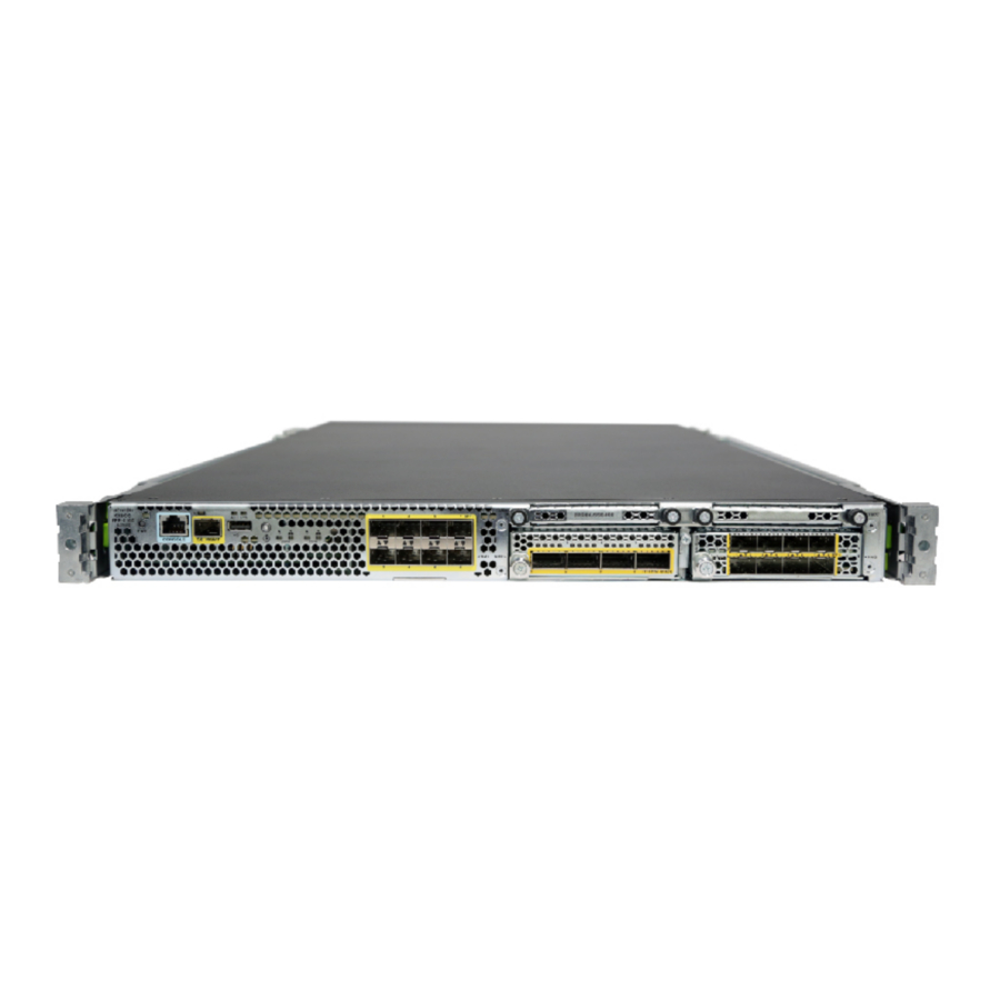
The following figure shows the Firepower 4100 series security appliance.
Figure 1: Firepower 4100 Series

The following table lists the features for the Firepower 4100 series.
Table 1: Firepower 4100 Series Features
| Feature | 4110 | 4120 | 4140 | 4150 |
| Form factor | 1 RU | |||
| Fits a standard 19-inch (48.3cm) square-hole rack | ||||
| Rack mount | Slide rails, mount ears, and screws included | |||
| 4-post Electronic Industries Association (EIA)-310-D rack | ||||
| Airflow | Front to rear Cold aisle to hot aisle | |||
| Processor | Single 12-core | Single 18-core | Single 22-core | |
| Memory | 64-GB DDR4 DRAM | 128-GB DDR4 DRAM | 256-GB DDR4 DRAM | 256-GB DDR4 DRAM |
| Maximum number of interfaces | 24 With two 8-port network modules installed | |||
| Management port | One Gigabit Ethernet Supports 1-Gb fiber or copper small form-factor pluggable (SFP) | |||
| Serial port | One RJ-45 console | |||
| USB port | One USB 2.0 Type A | |||
| Network ports | Eight fixed 1-Gb and 10-Gb SFP+ ports (named Ethernet 1/1 through 1/8) | |||
| Small form-factor pluggable (SFP) ports | Eight fixed 1-Gb and 10-Gb SFP+ ports See Supported SFP/SFP+ and QSFP Transceivers for a list of supported transceivers. | |||
| Pullout asset card | Displays the serial number; on the front panel | |||
| Grounding lug | On rear panel | |||
| Locator beacon | On front panel | |||
| Power switch | On rear panel | |||
| Network modules | Two network module slots (named network module 2 and network module 3) | |||
| Supported network modules |
| |||
| AC power supply | Two (1+1) power supply module slots Ships with one 400-W AC power supply modules Hot-swappable | Two (1+1) power supply module slots Ships with two 400-W AC power supply modules Hot-swappable | ||
| DC power supply | Optional | |||
| Redundant power | 1+1 | |||
| Fan | Six fan module slots 3+1 redundancy Hot-swappable | |||
| Storage | Two SSD slots Ships with one 200-GB SSD installed in slot 1. Slot 1 is the primary SSD and should always be present. Slot 1 is reserved for the logical device application instance (threat defense or ASA). Note RAID is not supported.  The SSD must be installed in slot 1. Slot 2 is optional and is reserved only for the Malware Storage Pack (MSP). | Two SSD slots Ships with one 400-GB SSD installed in slot 1. Slot 1 is the primary SSD and should always be present. Slot 1 is reserved for the logical device application instance (threat defense or ASA). Note RAID is not supported. The SSD must be installed in slot 1. Slot 2 is optional and is reserved only for the MSP. | ||
| MSP | Installed in the second SSD slot only | |||
| Security standards certifications |
See the "Security Certifications Compliance" chapter in the for the procedure to enable security modes. | |||
| Network Equipment Building Systems (NEBS) certification | — | Certified | — | — |
Deployment Options
Here are some examples of how you can deploy the Firepower 4100:
- In a data center using NGFW and ASA
- At the core/aggregation layer of a 3-tier data center in a high availability configuration
- As a dedicated multifunctional security service within converged infrastructure stacks, for example, vBlock, FlexPod, and so forth, at the access layer
- As a high-performance data center security appliance between the WAN edge and the data center core in a high availability configuration
- Inter-DC clustering deployments
- In newer spine/leaf data center designs, deployment as a leaf that exclusively offers security functions
Package Contents
The following figure shows the package contents for the Firepower 4100. Note that the contents are subject to change and your exact contents might contain additional or fewer items.
Figure 2: Firepower 4100 Package Contents

- Firepower 4100 chassis
- Blue console cable PC terminal adapter (part number 72-3383-01)
- Two power cords (country-specific) See Power Cord Specifications a list of supported power cords.
- 10/100/1000BASE-T SFP transceiver
- Ground lug kit (part number 69-1000359-01):
- One ground lug #6 AWG, 90 degree, #10 post (part number 32-0608-01)
- Two 10-32 x 39-8-inch Phillips Head screws (part number 48-0700-01)
- Cable management bracket kit (part number 69-100376-01)
- Two cable management brackets (part number 700-106377-01)
- Four 8-32 x 0.375-inch Phillips screws (part number 48-2696-01)
- Two slide rails with two M3 x 0.5 x 6-mm screws (48-101144-01)
- Two slide rail locking brackets (part number 700-105350-02) Six 8-32 x 0.375-inch Phillips screws (part number 48-2696-01)
- Artesyn tie wrap and tie wrap clamp (part number 52-100204-01)
- Flextronics tie wrap and tie wrap clamp (part number 52-100202-01)
- Cisco Secure Firepower 4100 This document has links to the hardware installation guide, regulatory and safety information guide, and warranty and licensing information. It also contains a QR code and URL that point to the Digital Documentation Portal. The portal contains links to the product information page, the hardware installation guide, the regulatory and safety information guide, and the getting started guide.
Serial Number Location
The serial number for the Firepower 4100 series chassis is located on the pullout asset card on the front panel.
Figure 3: Serial Number on the 4100 Chassis

You can also view additional model information on the compliance label located on the bottom of the chassis.
Front Panel Figure 4: Compliance Label on the 4100 Chassis

Front Panel
The following figure shows the front panel of the Firepower 4100.
Figure 5:Firepower 4100 Front Panel

- RJ-45 console port
- Gigabit Ethernet management port
- USB 2.0 Type A port
- Eight fixed SFP+ (1-Gb/10-Gb) ports (in network module slot 1) Ethernet 1/1 through 1/8 labeled top to bottom, left to right
- SSD 1 Reserved for the primary SSD; slot 1 must always be populated.
- SSD 2 Reserved for the optional MSP.
- Power LED
- Locator LED
- Pullout asset card
- Network module 2 Note The 10-Gb network module is shown.
- Network module 3 Note The 10-Gb network module is shown.
RJ-45 Console Port
The Firepower 4100 has a standard RJ-45 console port. You can use the CLI to configure your Firepower 4100 through the RJ-45 serial console port by using a terminal server or a terminal emulation program on a computer.
The RJ-45 (8P8C) port supports RS-232 signaling to an internal UART controller. The console port does not have any hardware flow control, and does not support a remote dial-in modem. The baud rate is 9600. You can use the standard cable found in your accessory kit to convert the RJ-45 to DB-9 if necessary.
Type A USB Port
You can use the external USB Type A port to attach a data storage device. The external USB drive identifier is disk1:. The USB Type A port supports the following:
- Hot swapping
- USB drive formatted with FAT32
- Boot kick-start image from the Supervisor ROMMON for discovery recovery purposes
- Copy files to and from workspace:/ and volatile:/ within local-mgmt. The most relevant files are:
- Core files
- Ethanalyzer packet captures
- Tech-support files
- Security module log files
- Platform bundle image upload usingdownload image usbA:
The USB Type A port does not support Cisco Secure Package (CSP) image upload.
Network Ports
The Firepower 4100 chassis has eight fixed ports that require 1-Gb/10-Gb SFP/SFP+ transceivers (fiber or copper). They are numbered from left to right starting with 1 and are named Ethernet 1/1 through Ethernet 1/8. The 4100 also has two network module slots that support different numbers of ports depending on the network module. See Network Modules for the supported network modules. See for Supported SFP/SFP+ and QSFP Transceivers the list of supported transceivers.
Each port has LEDs that represent link/activity status.
Management Port
The Firepower 4100 chassis has a management port that requires a 1-Gb fiber or copper SFP.
Front Panel LEDs
The following figure and table describe the Firepower 4100 front panel LEDs.
Figure 6:Front Panel LEDs

- Management
- Off—No connection or port is not in use.
- Amber—No link or network failure.
- Green—Link up.
- Green, flashing—Network activity.
- Health (SYS)
- Off—System is not booting yet.
- Green, flashing—Power-up diagnostics are complete and system is booting up.
- Green—The system has passed power-up diagnostics.
- Amber—Power-up diagnostics has failed.
- Amber, flashing—Alarm; power-up diagnostics are running.
- SSD
- Off— SSD not present.
- Green—SSD is present; no activity.
- Green, flashing—SSD is active.
- Amber—SSD failure.
- Amber, flashing—Rebuilding, flashes at 1 Hz.
- Amber, flashing—Predictive failure analysis (PFA) and hot spare; two fast flashes at 4 Hz, pause for 0.5 seconds.
- Power
- Off—Input power not detected.
- Green, flashing—Appears only when you move the power switch from ON to OFF. System is shutting down and powers off once shutdown is completed.
- Amber—System is powering up.
- Green—System fully powered up.
- Amber, flashing—Reserved.
- Active (ACT) This LED is not supported; reserved for future use.
- Locator LED
- Off—Locate is off.
- Blue—Locate is on.
- Network activity
- Off—No connection or port is not in use.
- Amber—No link or network failure.
- Green—Link up.
- Green, flashing—Network activity.
Rear Panel
The following figure shows the rear panel of the Firepower 4100.
Figure 7: Firepower 4100 Rear Panel

- Power on/off switch
- Power supply module 1
- Power supply module 2
- Fan module 1
- Fan module 2
- Fan module 3
- Fan module 4
- Fan module 5
- Fan module 6
- Location for the two-post grounding lug Note The two-post grounding lug is included in the accessory kit.
The power switch is located to the left of power supply module 1 on the rear of the chassis. It is a toggle switch that controls power to the system. If the power switch is in standby position, only the 3.3-V standby power is enabled from the power supply module and the 12-V main power is OFF. When the switch is in the ON position, the 12-V main power is turned on and the system boots.
You can shut down the chassis in one of two ways:
- Perform a graceful shutdown using the shutdown commands. This may take several minutes to complete. Then toggle the power switch to the OFF position. The power LED changes from solid green to off immediately.
If you move the power switch to the OFF position before the shutdown command sequence is complete or if you remove the system power cords before the graceful shutdown is complete, disk corruption can occur.
Network Modules
- Toggle the power switch to the OFF position. The power LED changes from solid green to off.
Note
After removing power from the chassis either by moving the power switch to OFF or unplugging the power cord, wait at least 10 seconds before turning power back ON.
Network Modules
The Firepower 4100 contains two network module slots that provide optical or electrical network interfaces. Network modules are optional, removable I/O modules that provide either additional ports or different interface types (1/10/40 Gb). The Firepower network modules plug into the chassis on the front panel.
For More Information
- See 10-Gb Network Module for a description of the 10-GB network module.
- See 40-Gb Network Module for a description of the 40-GB network module.
- See Hardware Bypass Network Modules for the location and description of the LEDs, and the port configurations for the hardware bypass network modules.
- See Install, Remove, and Replace the Network Module for the procedure for removing and replacing network modules.
10-Gb Network Module
The following figure shows the front panel of the 10-Gb single-wide network module (FPR4K-NM-8X10G). The eight ports are numbered from top to bottom, left to right.
Note
Make sure you have the correct firmware package and software version installed to support this network module.
Note
The FPR4K-NM-8X10G is NEBS-compliant.
Note
You can fit four copper SFPs in either the top row of ports or the bottom row of ports. Both rows cannot be populated at the same time, because of the port row spacing.
Figure 8: FPR4K-NM-8X10G

- Captive screw/handle
- Ethernet X/1
- Ethernet X/3
- Ethernet X/5
- Ethernet X/7
- Ethernet X/2
- Ethernet X/4
- Ethernet X/6
- Ethernet X/8
- Network activity LEDs
- Off—No connection or port is not in use.
- Amber—No link or network failure.
- Green—Link up.
- Green, flashing—Network activity.
For More Information
- For a list of copper SFPs, see Supported SFP/SFP+ and QSFP Transceivers.
40-Gb Network Module
The following figure shows the front panel of the 40-Gb network module (FPR4K-NM-4X40G.) The FPR4K-NM-4X40G is a single-wide module that supports hot swapping. The four ports are numbered left to right.
Note
Make sure you have the correct firmware package and software version installed to support this network module.
Note
The FPR4K-NM-4X40G is NEBS-compliant.
Figure 9: FPR4K-NM-4X40G

- Captive screw/handle
- Network activity LEDs
- Off—No connection or port is not in use.
- Amber—No link or network failure.
- Green—Link up.
- Green, flashing—Network activity.
- 40Gb—Only the leftmost LED indicates the port status.
- 4x10Gb—Each of the port LEDS indicates the status of respective 10-Gb channel.
- Ethernet X/1
- Ethernet X/2
- Ethernet X/3
- Ethernet X/4
Hardware Bypass Network Modules
Hardware bypass (also known as fail-to-wire) is a physical layer (Layer 1) bypass that allows paired interfaces to go into bypass mode so that the hardware forwards packets between these port pairs without software intervention. Hardware bypass provides network connectivity when there are software or hardware failures. Hardware bypass is useful on ports where the Firepower security appliance is only monitoring or logging traffic. The hardware bypass network modules have an optical switch that is capable of connecting the two ports when needed. The hardware bypass network modules have built-in SFPs.
Hardware bypass is supported only on a fixed set of ports. You can pair Port 1 with Port 2, Port 3 with Port 4, but you cannot pair Port 1 with Port 4 for example.
Note
When the appliance switches from normal operation to hardware bypass or from hardware bypass back to normal operation, traffic may be interrupted for several seconds. A number of factors can affect the length of the interruption; for example, behavior of the optical link partner such as how it handles link faults and debounce timing; spanning tree protocol convergence; dynamic routing protocol convergence; and so on. During this time, you may experience dropped connections.
There are three configuration options for hardware bypass network modules:
- Passive interfaces—Connection to a single port.
For each network segment you want to monitor passively, connect the cables to one interface. This is how the nonhardware bypass network modules operate. - Inline interfaces—Connection to any two like ports (10 Gb to 10 Gb for example) on one network module, across network modules, or fixed ports.
For each network segment you want to monitor inline, connect the cables to pairs of interfaces. - Inline with hardware bypass interfaces—Connection of a hardware bypass paired set.
For each network segment that you want to configure inline with fail-open, connect the cables to the paired interface set.
For the 40-Gb network module, you connect the two ports to form a paired set. For the 1/10-Gb network modules, you connect the top port to the bottom port to form a hardware bypass paired set. This allows traffic to flow even if the security appliance fails or loses power.
Note
If you have an inline interface set with a mix of hardware bypass and nonhardware bypass interfaces, you cannot enable hardware bypass on this inline interface set. You can only enable hardware bypass on an inline interface set if all the pairs in the inline set are valid hardware bypass pairs.
For More Information
- See 1-Gb Network Module with Hardware Bypass for a description of the 1-Gb network module.
- See 40-Gb Network Module with Hardware Bypass for a description of the 40-Gb network module.
- See 1-Gb SX/10-Gb SR/10-Gb LR Network Module with Hardware Bypass for a description of the 1-Gb SX, 10-Gb SR and LR network modules.
- See Install, Remove, and Replace the Network Module for the procedure for removing and replacing single-wide network modules.
1-Gb Network Module with Hardware Bypass
The following figure shows the front panel view of the 1-Gb network module with hardware bypass (FPR-NM-8X1G-F). Pair ports 1 and 2, 3 and 4, 5 and 6, and 7 and 8 to form hardware bypass paired sets.
Note
Make sure you have the correct firmware package and software version installed to support this network module.
Figure 10: FPR-NM-8X1G-F

- Captive screw/handle
- Bypass LEDs B1 through B4
- Green—In standby mode.
- Amber, flashing—Port is in hardware bypass mode, failure event.
- Ethernet X/1 Ports 1 and 2 are paired together to form a hardware bypass pair. LED B1 applies to this paired port.
- Ethernet X/2 Ports 3 and 4 are paired together to form a hardware bypass pair. LED B2 applies to this paired port.
- Ethernet X/2 Ports 5 and 6 are paired together to form a hardware bypass pair. LED B3 applies to this paired port.
- Ethernet X/2 Ports 7 and 8 are paired together to form a hardware bypass pair. LED B4 applies to this paired port.
- Network activity LEDs
- Left LED—Green indicates network activity when a 10M/100M/1G connection is made.
- Right LED—Not in use at this time.
40-Gb Network Module with Hardware Bypass
The following figure shows the front panel of the 40-Gb hardware bypass network module
(FPR4K-NM-2X40G-F). The FPR4K-NM-2X40G-F is a single-wide module that does not support hot swapping. The two ports are numbered left to right. Pair the two ports to create a hardware bypass paired set.
Note
Make sure you have the correct firmware package and software version installed to support this network module.
Figure 11: FPR4K-NM-2X40G-F

- Captive screw/handle
- Port 1 Ethernet X/1 Ports 1 and 2 are paired together to form a hardware bypass pair.
- Port 2 Ethernet X/2 Ports 1 and 2 are paired together to form a hardware bypass pair.
- Port 1 network activity LEDs:
- Amber—No connection, or port is not in use, or no link or network failure.
- Green—Link up, no network activity.
- Green, flashing—Network activity.
- BP (bypass LED):
- Green—In standby mode.
- Amber, flashing—Port is in hardware bypass mode, failure event.
- Port 2 network activity LEDs:
- Amber—No connection, or port is not in use, or no link or network failure.
- Green—Link up, no network activity.
- Green, flashing—Network activity.
The following table describes the cable specifications needed to keep the insertion loss as low as possible.
Table 2: 40-Gb BASE-SR Cable Specifications
| Interface | Supported Cable |
| Ethernet 40-G BASE-SR4 | 50 microns core diameter |
| 850 nm wavelength | 2000/4700 (OM3/4) modal bandwidth (MHz*km) |
| MPO-12 port adapter | 50 m cable distance |
Note
See the specifications of the QSFP for the 40-Gb BASE-SR-4.
We recommend the following Cisco OM3 MTP/MPO cables.
Table 3: Cisco Cables
| Cisco Part Number | Cable Length |
| CAB-ETH-40G-5M | 5 m |
| CAB-ETH-40G-10M | 10 m |
| CAB-ETH-40G-20M | 20 m |
1-Gb SX/10-Gb SR/10-Gb LR Network Module with Hardware Bypass
The following figure shows the front panel of the 1-Gb SX, 10-Gb SR and 10-Gb LR hardware bypass network modules (FPR4K-NM-6X1SX-F, FPR4K-NM-6X10SR-F, FPR4K-NM-6X10LR-F). This is a single-wide module that does not support hot swapping. The six ports are numbered from top to bottom, left to right. Pair ports 1 and 2, 3 and 4, and 5 and 6 to form hardware bypass paired sets.
Note
Make sure you have the correct firmware package and software version installed to support this network module.
Figure 12: FPR4K-NM-6X1SX-F, FPR4K-NM-6X10SR-F, FPR4K-NM-6X10LR-F

- Captive screw/handle
- Six network activity LEDs:
- Amber—No connection, or port is not in use, or no link or network failure.
- Green—Link up, no network activity.
- Green, flashing—Network activity.
- Ethernet X/1 (top port) Ethernet X/2 (bottom port) Ports 1 and 2 are paired together to form a hardware bypass pair.
- Ethernet X/3 (top port) Ethernet X/4 (bottom port) Ports 3 and 4 are paired together to form a hardware bypass pair.
- Ethernet X/5 (top port) Ethernet X/6 (bottom port) Ports 5 and 6 are paired together to form a hardware bypass pair.
- Bypass LEDs B1 through B3:
- Green—In standby mode.
- Amber, flashing—Port is in hardware bypass mode, failure event.
The 1-Gb SX /10-Gb SR/10-Gb LR network modules have the following insertion loss measurements. Insertion loss measurements help you to troubleshoot the network by verifying cable installation and performance.
Table 4: 1-Gb SX Network Module (FPR4K-NM-6X1SX-F)
| Operating Mode | Typical | Maximum | |
| Insertion loss | Normal | 0.9 dB | 1.4 dB |
| Hardware bypass | 1.2 dB | 1.7 dB | |
| Core diameter (microns) | Modal bandwidth (MHz/km) | Cable distance Note Half the distance specified by the IEEE standard. | |
| Cable and operating distance | 62.5 | 160 (FDDI) | 110 m |
| 62.5 | 200 (OM1) | 137 m | |
| 50 | 400 | 250 m | |
| 50 | 500 (OM2) | 275 m | |
| 50 | 2000 (OM3) | 500 m |
Table 5: 10-Gb SR Network Module (FPR4K-NM-6X10SR-F)
| Operating Mode | Typical | Maximum | |
| Insertion loss | Normal | 0.9 dB | 1.4 dB |
| Hardware bypass | 1.2 dB | 1.7 dB | |
| Core diameter (microns) | Modal bandwidth (MHz/km) | Cable distance Note Half the distance specified by the IEEE standard. | |
| Cable and operating distance | 62.5 | 160 (FDDI) | 13 m |
| 62.5 | 200 (OM1) | 16.5 m | |
| 50 | 400 | 33 m | |
| 50 | 500 (OM2) | 41 m | |
| 50 | 2000 (OM3) | 150 m | |
| 50 | 4700 (OM4) | 200 m |
Table 6: 10-Gb LR Network Module (FPR4K-NM-6X10LR-F)
| Operating Mode | Typical | Maximum | |
| Insertion loss | Normal | 1.2 dB | 1.6 dB |
| Hardware bypass | 1.5 dB | 1.9 dB | |
| Core diameter (microns) | Modal bandwidth (MHz/km) | Cable distance Note Half the distance specified by the IEEE standard. | |
| Cable and operating distance | G.652 | Single mode | 5 km |
Power Supply Modules
The Firepower 4100 supports two AC or DC power supply modules so that dual power supply redundancy protection is available. Facing the back of the chassis, the power supply modules are numbered left to right, for example, PSU1 and PSU2.
Note
Do not mix AC and DC power supply modules in one chassis.
Note
After removing power from the chassis either by moving the power switch to OFF or unplugging the power cord, wait at least 10 seconds before turning power back ON.
 Attention
Make sure that one power supply module is always active.
See Remove and Replace the Power Supply Module for the procedure for removing and replacing the power supply module.
AC Power Supply
The power supplies can supply up to 1100-W power across the input voltage range. The load is shared when both power supply modules are plugged in and running at the same time. The power supply modules are hot-swappable.
Table 7: AC Power Supply Module Hardware Specifications
| Description | Specification |
| Input voltage | 100 to 240 V AC |
| Maximum current | 13 A (at 100 V AC) Note The system power requirements are lower than the power supply module capabilities. See Hardware Specifications for the system power requirements. |
| Maximum output power | 1100 W |
| Frequency | 50 to 60 Hz |
| Redundancy | 1+1 redundant |
| Efficiency at 50% load | 92% |
DC Power Supply
The power supplies can supply up to 950 W of power across the input voltage range. The load is shared when both power supply modules are plugged in and running at the same time. The power supply modules are hot-swappable.
Table 8: DC Power Supply Module Hardware Specifications
| Description | Specification |
| Input voltage | -40 to -60 V DC |
| Maximum current | 26 A (at 40 V DC) |
| Maximum output power | 950 W |
| Redundancy | 1+1 redundant |
| Efficiency at 50% load | 92% |
Power Supply Module LEDs
The following figure shows the two-color power supply LEDs. The LEDs are located on the upper right side.
Figure 13: Power Supply Module LEDs

- Amber FAIL LED
- Green OK LED
The following table describes the power module supply LEDs and their states.
Table 9: Power Supply Module LEDs
| Amber LED (Fail Status) | Green LED (OK Status) | |
| No power to all power supplies | Off | Off |
| Power supply module failure Includes overvoltage, overcurrent, overtemperature, and fan failure | On | Off |
| Power supply module warning events Power supply continues to operate. With high temperature, high power, and slow fan | 1 Hz flashing | Off |
| Power is present. 3.3 VSB on (power supply module off) | Off | 1 Hz flashing |
| Power supply module is OK and on. | Off | On |
Fan Modules
The Firepower 4100 requires six fan modules, which are hot-swappable. They are installed in the rear of the chassis. The system supports operation with a single fan failure (N+1 fan redundancy), but do not run the system for an extended amount of time without all fan modules installed. Keep removal and replacement time at three minutes. Remove and replace one fan module at a time.
If you remove a fan or a fan fails, the other fans operate at full speed, which can be noisy.
The fan modules are numbered left to right, for example, FAN1, FAN2, FAN3, FAN4, FAN5, and FAN6. See Remove and Replace the Fan Module for the procedure for removing and replacing the fan module.
The following figure shows the location of the fan LED.
Figure 14: Fan LED

- Two-color LED
The fan module has one two-color LED, which is located on the upper left corner of the fan.
- Amber—Fan failure.
- Green—Fan running normally. It may take up to one minute for the LED status to turn green after power is on.
Supported SFP/SFP+ and QSFP Transceivers
The SFP/SFP+ transceivers are bidirectional devices with a transmitter and receiver in the same physical package. It is a hot-swappable optical or electrical (copper) interface that plugs into the SFP/SFP+ ports on the fixed ports and the network module ports, and provides Ethernet connectivity.

Use appropriate ESD procedures when inserting the transceiver. Avoid touching the contacts at the rear, and keep the contacts and ports free of dust and dirt. Keep unused transceivers in the ESD packing that they were shipped in. The following figure shows a sample SFP transceiver.
Figure 15: SFP

- Dust plug
- Bail clasp
- Receive optical bore
- Transmit optical bore
Safety Warnings
Take note of the following optical connection warnings:

Statement 1051—Laser Radiation
Invisible laser radiation may be emitted from disconnected fibers or connectors. Do not stare into beams or view directly with optical instruments.
Statement 1055—Class 1/1M Laser
Invisible laser radiation is present. Do not expose to users of telescopic optics. This applies to Class 1/1M laser products.

For some earlier production Firepower 4100 chassis, you may experience difficulty using the GLC-TE SFP on the management port or fixed ports. Contact Cisco TAC for support if you encounter problems with the GLC-TE SFP.
The following table lists the Cisco supported transceivers.
Table 10: Supported Cisco SFP/SFP+ Transceivers
| Optics Type | PID |
| 1 Gb | |
| 1G-SX | GLC-SX-MMD |
| 1G-LH/LX | GLC-LH-SMD |
| 1G-EX | GLC-EX-SMD |
| 1G-ZX | GLC-ZX-SMD |
| 1G 1000Base-T | GLC-T |
| 1G 1000Base-T | GLC-TE |
| 10 Gb | |
| 10G-SR | SFP-10G-SR |
| 10G-SR-S | SFP-10G-SR-S |
| 10G-LR | SFP-10G-LR |
| 10G-LR-S | SFP-10G-LR-S |
| 10G-LRM | SFP-10G-LRM |
| 10G-ER | SFP-10G-ER |
| 10G-ER-S | SFP-10G-ER-S |
| 10G-ZR-S | SFP-10G-ZR-S |
| 10G Cu, 1m | SFP-H10GB-CU1M |
| 10G Cu, 1.5m | SFP-H10GB-CU1-5M |
| 10G Cu, 2m | SFP-H10GB-CU2M |
| 10G Cu, 2.5m | SFP-H10GB-CU2-5M |
| 10G Cu, 3m | SFP-H10GB-CU3M |
| 10G Cu, 5m | SFP-H10GB-CU5M |
| 10G Cu, 7m | SFP-H10GB-ACU7M |
| 10G Cu, 10m | SFP-H10GB-ACU10M |
| 10G AOC, 1m | SFP-10G-AOC1M |
| 10G AOC, 2m | SFP-10G-AOC2M |
| 10G AOC, 3m | SFP-10G-AOC3M |
| 10G AOC, 5m | SFP-10G-AOC5M |
| 10G AOC, 7m | SFP-10G-AOC7M |
| 10G AOC, 10m | SFP-10GAOC10M |
| 40 Gb | |
| 40G-SR4 | QSFP-40G-SR4 |
| 40G-SR4-S | QSFP-40G-SR4-S |
| 40G-CSR4 | QSFP-40G-CSR4 |
| 40G-SR-BD | QSFP-40G-SR-BD |
| 40GE-LR4 | QSFP-40GE-LR4 |
| 40GE-LR4-S | QSFP-40GE-LR4-S |
| 40G-LR4L | WSP-Q40GLR4L |
| 40G-CU, 1M, 3M, 5M | QSFP-H40G-CU |
| 40G-4X10G-CU, 1M, 3M, 5M | QSFP-4SFP10G-CU |
| 40G-CU-A, 7M, 10M | QSFP-H40G-ACU |
| 40G-4X10G-CU-A, 7M, 10M | QSFP-4X10G-AC |
| 40G-AOC, 1M, 2M, 3M, 5M, 7M, 10M, 15M | QSFP-H40G-AOC |
Hardware Specifications
The following table contains hardware specifications for the Firepower 4100.
Table 11: Firepower 4100 Hardware Specifications


Product ID Numbers
The following table lists the PIDs associated with the Firepower 4100 series. All of the PIDs in the table are field-replaceable. If you need to get a return material authorization (RMA) for any component, see Cisco Returns Portal for more information.
Table 12: Firepower 4100 Series PIDs
| PID | Description |
| FPR4110-AMP-K9 | Cisco Firepower 4110 AMP appliance, 1 RU, two network module bays |
| FPR4110-ASA-K9 | Cisco Firepower 4110 ASA appliance, 1 RU, two network module bays |
| FPR4110-NGFW-K9 | Cisco Firepower 4110 NGFW appliance, 1 RU, two network module bays |
| FPR4110-NGIPS-K9 | Cisco Firepower 4110 NGIPS appliance, 1 RU, two network module bays |
| FPR4120-AMP-K9 | Cisco Firepower 4120 AMP appliance, 1 RU, two network module bays |
| FPR4120-ASA-K9 | Cisco Firepower 4120 ASA appliance, 1 RU, two network module bays |
| FPR4120-NGFW-K9 | Cisco Firepower 4120 NGFW appliance, 1 RU, two network module bays |
| FPR4120-NGIPS-K9 | Cisco Firepower 4120 NGIPS appliance, 1 RU, two network module bays |
| FPR4140-AMP-K9 | Cisco Firepower 4140 AMP appliance, 1 RU, two network module bays |
| FPR4140-ASA-K9 | Cisco Firepower 4140 ASA appliance, 1 RU, two network module bays |
| FPR4140-NGFW-K9 | Cisco Firepower 4140 NGFW appliance, 1 RU, two network module bays |
| FPR4140-NGIPS-K9 | Cisco Firepower 4140 NGIPS appliance, 1 RU, two network module bays |
| FPR4150-AMP-K9 | Cisco Firepower 4150 AMP appliance, 1 RU, two network module bays |
| FPR4150-ASA-K9 | Cisco Firepower 4150 ASA appliance, 1 RU, two network module bays |
| FPR4150-NGFW-K9 | Cisco Firepower 4150 NGFW appliance, 1 RU, two network module bays |
| FPR4150-NGIPS-K9 | Cisco Firepower 4150 NGIPS appliance, 1 RU, two network module bays |
| FPR4K-ACC-KIT | Firepower hardware accessory kit containing rack mounts and cables |
| FPR4K-ACC-KIT= | Firepower hardware accessory kit containing rack mounts and cables (spare) |
| FPR4K-ASA-CAR | License to add carrier security to ASA on the Firepower 4100 |
| FPR4K-FAN | Fan |
| FPR4K-FAN= | Fan (spare) |
| FPR4K-NM-2X40G-F | 2-port 40-Gb SR hardware bypass network module |
| FPR4K-NM-2X40G-F= | 2-port 40-Gb SR hardware bypass network module (spare) |
| FPR4K-NM-4X40G | 4-port 40-Gb QSFP+ network module |
| FPR4K-NM-4X40G= | 4-port 40-Gb QSFP+ network module (spare) |
| FPR4K-NM-6X10LR-F | 6-port 10-Gb LR hardware bypass network module |
| FPR4K-NM-6X10LR-F= | 6-port 10-Gb LR hardware bypass network module (spare) |
| FPR4K-NM-6X10SR-F | 6-port 10-Gb SR hardware bypass network module |
| FPR4K-NM-6X10SR-F= | 6-port 10-Gb SR hardware bypass network module (spare) |
| FPR4K-NM-6X1SX-F | 6-port 1-Gb SX fiber hardware bypass network module |
| FPR4K-NM-6X1SX-F= | 6-port 1-Gb SX fiber hardware bypass network module (spare) |
| FPR4K-NM-8X10G | 8-port 10-Gb SFP+ network module |
| FPR4K-NM-8X10G= | 8-port 10-Gb SFP+ network module (spare) |
| FPR4K-NM-8X1G-F | 8-port 1-Gb copper hardware bypass network module |
| FPR4K-NM-8X1G-F= | 8-port 1-Gb copper hardware bypass network module (spare) |
| FPR4K-NM-BLANK | Network module blank slot cover |
| FPR4K-NM-BLANK= | Network module blank slot cover (spare) |
| FPR4K-PSU-BLANK | Chassis power supply module blank slot cover |
| FPR4K-PSU-BLANK= | Chassis power supply module blank slot cover (spare) |
| FPR4K-PWR-AC-1100 | 1100W AC power supply module |
| FPR4K-PWR-AC-1100- | 1100W AC power supply module (spare) |
| FPR4K-PWR-DC-950 | 950W DC power supply module |
| FPR4K-PWR-DC-950= | 950W DC power supply module (spare) |
| FPR4K-RACK-MNT | Rack mount kit |
| FPR4K-RACK-MNT= | Rack mount kit (spare) |
| FPR4K-SSD-BBLKD | SSD slot carrier |
| FPR4K-SSD-BBLKD= | SSD slot carrier (spare) |
| FPR4K-SSD200 | 200-GB SSD for Firepower 4110 and 4120 |
| FPR4K-SSD200= | 200-GB SSD for Firepower 4110 and 4120 (spare) |
| FPR4K-SSD400 | 400-GB SSD for Firepower 4140 and 4150 |
| FPR4K-SSD400= | 400-GB SSD for Firepower 4140 and 4150 (spare) |
Power Cord Specifications
Each power supply has a separate power cord. Standard power cords are available for connection to the security appliance.
If you do not order the optional power cord with the system, you are responsible for selecting the appropriate power cord for the product. Using a incompatible power cord with this product may result in electrical safety hazard. Orders delivered to Argentina, Brazil, and Japan must have the appropriate power cord ordered with the system.
Note
Only the approved power cords or jumper power cords provided with the security appliance are supported.
The following power cords are supported.
Figure 16: Argentina CAB-9K10A-AR

- Plug: IRAM 2073
- Cord set rating: 10 A, 250 V
- Connector: IEC 60320-C15
Figure 17: Australia CAB-9K10A-AU

- Plug: A.S. 3112-2000
- Cord set rating: 10 A, 250 V
- Connector: IEC 60320-C15
Figure 18: Brazil CAB-250V-10A-BR

- Plug: EL223 (NBR 14136)
- Cord set rating: 10 A, 250 V
- Connector: EL 701B (EN 60320/C13)
Figure 19: Brazil PWR-CORD-G2A-BZ

- Plug: NBR 14136
- Cord set rating: 10 A, 250 V
- Connector: IEC 60320-C13
Figure 20: China CAB-9K10A-CH

- Plug: CCC GB2099.1, GB1002
- Cord set rating: 10 A, 250 V
- Connector: IEC 60320-C15
Figure 21: Denmark CAB-TA-DN

- Plug: DK3
- Cord set rating: 10 A, 250 V
- Connector: IEC 60320-C13
Figure 22: Europe CAB-AC-EUR

- Plug: CEE 7/7
- Cord set rating: 10 A, 250 V
- Connector: IEC 60320-C15
Figure 23: India CAB-250V-10A-ID

- Plug: IS 6538-1971
- Cord set rating: 10 A, 250 V
- Connector: IEC 60320-C13
Figure 24: Israel CAB-250V-10A-IS

- Plug: SI-32
- Cord set rating: 10 A, 250 V
- Connector: IEC 60320-C13
Figure 25: Italy CAB-9K10A-IT

- Plug: CEI 23-16/VII
- Cord set rating: 10 A, 250 V
- Connector: IEC 60320-C15
Figure 26: Korea CAB-9K10A-KOR

- Plug: CEE 7/7
- Cord set rating: 10 A, 250 V
- Connector: IEC 60320-C19
Figure 27: Japan CAB-L620P-C13-JPN

- Plug: NEMA L6-20P
- Cord set rating: 15 A, 250 V
- Connector: IEC 60320-C13
Figure 28: Japan CAB-TA-JP

- Plug: NEMA5-15P/JIS 8303
- Cord set rating: 12 A, 125 V
- Connector: IEC 60320-C15
Figure 29: North America CAB-TA-NA

- Plug: NEMA5-15P
- Cord set rating: 12 A, 125 V
- Connector: IEC 60320-C15
Figure 30: Saudi Arabia ATA187PWRCORD-SAUD

- Plug: BS1363A/SS145
- Cord set rating: 10 A, 250 V
- Connector: IEC 60320-C13
Figure 31: South Africa CAB-9K10A-SA

- Plug: SABS 164
- Cord set rating: 10 A, 250 V
- Connector: IEC 60320-C15
Figure 32: Switzerland CAB-9K10A-SW

- Plug: SEV 1011
- Cord set rating: 10 A, 250 V
- Connector: IEC 60320-C15
Figure 33: Taiwan CAB-9K10A-TWN

- Plug: CNS10917-2
- Cord set rating: 10 A, 125 V
- Connector: IEC 60320-C15
Figure 34: United Kingdom CP-PWR-CORD-UK

- Plug: BS1363A/SS145
- Cord set rating: 10 A, 250 V
- Connector: IEC 60320-C13
Documents / Resources
References
Download manual
Here you can download full pdf version of manual, it may contain additional safety instructions, warranty information, FCC rules, etc.
Download Cisco Firepower 4100 Series, Firepower 4110 / 4120 4140 / 4150 Manual
Advertisement


Need help?
Do you have a question about the Firepower 4100 Series and is the answer not in the manual?
Questions and answers