Advertisement
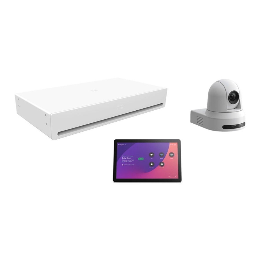
- 1 Box contents
- 2 Can be ordered separately
- 3 Safety and mounting hardware
- 4 Ventilation
- 5 Mount the codec in a rack
- 6 Connect the antennas to the codec
- 7 Connect the codec cables
- 8 Connect the camera cables
- 9 Turn on the codec
- 10 Complete the software setup
- 11 Product Overview
- 12 Documents / Resources
Box contents


- Power adapter and cable for PTZ 4K
- Ethernet cable for Room Navigator
- Antennas for Codec Pro
- Power cable for Codec Pro *
- Rack ears for Codec Pro (optional)

* No power cord option for Codec Pro: When the optional power cord is not ordered with the system, the customer is responsible for selecting the appropriate power cord to be used with this product. Using a non-compatible power cord with this product may result with electrical safety hazard. For orders to be delivered to Argentina, Brazil and Japan, appropriate power cord must be ordered with the system.
Rating of the power cable: 10 A, 250 V
Power connector: EL 701B (IEC 60320/C13)

Can be ordered separately
- Wall mounting bracket for the PTZ 4K camera.
- Ceiling mount for the PTZ 4K camera.
- Cisco table or ceiling microphone.
- HDMI and Ethernet cables. We recommend cables from Cisco. Use certified HDMI cables for the cameras and presentation sources (High Speed HDMI 1.4b) and for the screens (Premium High Speed HDMI). You need Ethernet cables for camera control and network (not required if using Wi-Fi).
Safety and mounting hardware
The wall and mounting hardware must be able to safely support the product.
The wall mounted system must be installed by qualified personnel, in accordance with state and local building regulations.
Ventilation

Do not block any ventilation openings on the codec. Minimum 10 cm / 4" free space in front and rear side of the unit. Minimum 4.5 cm / 1.7" free space below the codec and an adjacent rack-mounted component.
Mount the codec in a rack
(optional)
You can mount the rack ears so that the connector panel is facing forward or backward.

 Always use the power supplies for the PTZ 4K camera specified in www.cisco.com/go/PTZ4K-datasheet.
Use an Ethernet cable for camera control. Don't use a VISCA cable as it will cause severe damage to the camera.


Connect the antennas to the codec

Connect the codec cables

Connect the camera cables

Turn on the codec


Power (100-240 VAC, 50/60 Hz)
- Always use the provided power cable or use a power cable that meets the requirements of the power specification of the codec.
- Keep the power plug and outlet easily accessible in case you need to disconnect the device from power.
- This device is designed for connection to TN and IT power systems.

Network connectivity: Use either Ethernet LAN or Wi-Fi. Non-radio devices, which have the letters 'NR' in their product identifier (PID), don't support Wi-Fi.
 When the PTZ 4K is mounted upside down, configure the codec to flip the camera image. See the Administrator Guide for the codec.
Complete the software setup
- Turn on the screen. See the user documentation for the screen if HDMI input must be set manually.
- The system powers up automatically. If the system doesn't power up, check the power switch on the codec.
- When you see the Welcome screen, follow the instructions to complete the setup.

- We recommend that you upgrade the software on your Codec Pro before putting it to use. See the Administrator Guide for the codec: https://www.cisco.com/go/roomkit-docs

Product Overview

Cisco Codec Pro
- Antenna connector
- 6 × Line output (Euroblock, 3.5 mm)
- 8 × Microphone/Line input (Euroblock, 3.5 mm)
- GPIO port (Euroblock, 3.5 mm)
- COM port (Euroblock, 3.5 mm)
- Antenna connector
- Ground (Protective earth)
- Main power input (1.3 - 0.6 A, 100-240 V ac, 50/60 Hz)
- 2 × HDMI output with audio and video (Connector 1-2), 4Kp60
- HDMI output with audio and video (Connector 3), 4Kp30
- 2 × Camera input (HDMI, Connector 1-2), 1080p60
- 3 × HDMI input with audio and video (Connector 3-5), 4Kp30
- Camera input (3G-SDI / HD-SDI, Connector 6), 1080p60, HD-BNC, 75 Ω
- 2 × USB 2.0, type A
- USB 2.0, type B
- Maintenance (micro USB)
- Factory reset
- Network (Ethernet) 1Gb
- 2 × Camera control (Ethernet)
- Ethernet PoE - Internal network port for PoE device
- Touch panel (user interface, Ethernet PoE)
- Status LED
- Power On/Off
Cisco PTZ 4K


- Kensington lock
- Factory reset
- System select (Position: 61)
- HDMI output, 1080p60
- Camera control (Ethernet)
- Power input (12 Vdc, 2.5 A)
- Earth terminal
- Tripod screw hole2
- Screw holes for ceiling mounting
1 VISCA is enabled on HDMI output
2 Don't install the camera using the tripod screw and tripod screw hole for ceiling installation.
Room Kit Pro PTZ 4K Integrator Bundle Data Sheet
See the product data sheet for more information on ordering accessories, cables, and spare parts.
Visit these websites to learn more about your device.

help.webex.com


Cisco Systems Inc.
Corporate Headquarters
170 West Tasman Dr.
San Jose, CA 95134
USA
https://www.cisco.com/go/offices
Documents / Resources
References
Cisco Room Series - Cisco
Contact Cisco - Cisco
Webex PTZ 4K Camera Data Sheet - Cisco
Cisco Room Series - Cisco
![projectworkplace.cisco.com]() Cisco Workspaces: Video devices for every meeting room.
Cisco Workspaces: Video devices for every meeting room.![cs.co]() RoomOS for Collab Devices
RoomOS for Collab Devices![cs.co]() Brandfolder - Digital Asset Management Simplified.
Brandfolder - Digital Asset Management Simplified.
Download manual
Here you can download full pdf version of manual, it may contain additional safety instructions, warranty information, FCC rules, etc.
Advertisement


Need help?
Do you have a question about the Room Kit Pro and is the answer not in the manual?
Questions and answers