Table of Contents
Advertisement
Quick Links
F-Series - Field mounted indicators for safe and hazardous areas.
The Netherlands
The Netherlands
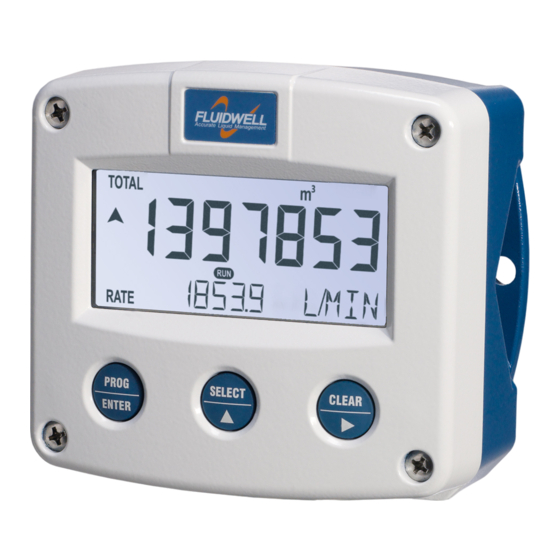
F116-P
DIFFERENTIAL / SUM FLOW COMPUTER
with analog and pulse outputs
Signal input flowmeter: pulse, Namur and coil
Signal outputs: (0)4-20mA / 0-10V ref. flow rate and pulse ref. total and
negative flow
Options: Intrinsically safe, Modbus communication and backlight
Fluidwell bv - © 2022 – FW_F116-P_M_v2201-01_EN.docx
More info: www.fluidwell.com/fseries
Advertisement
Table of Contents

Related Manuals for Fluidwell F116-P


Summary of Contents for Fluidwell F116-P
- Page 1 Signal outputs: (0)4-20mA / 0-10V ref. flow rate and pulse ref. total and negative flow Options: Intrinsically safe, Modbus communication and backlight F-Series - Field mounted indicators for safe and hazardous areas. Fluidwell bv - © 2022 – FW_F116-P_M_v2201-01_EN.docx The Netherlands The Netherlands More info: www.fluidwell.com/fseries...
-
Page 2: Safety Instructions
The F116-P must be installed in accordance with the EMC guidelines (Electro Magnetic Compatibility). • Connect a proper grounding to the metal enclosure as indicated if the F116-P has an incoming power or signal line which carries a hazardous live voltage. The Protective Earth (PE) wire may never be disconnected or removed. -
Page 3: About The Manual
This manual describes the standard unit as well as the available options. For additional information, please contact your supplier. A hazardous situation may occur if the F116-P is not used for the purpose it was designed for or is used incorrectly. Please carefully note the information in this manual indicated by the pictograms: A "warning !"... -
Page 4: Table Of Contents
Page 4 TABLE OF CONTENTS SAFETY INSTRUCTIONS........................2 DISPOSAL OF ELECTRONIC WASTE ....................2 SAFETY RULES AND PRECAUTIONARY MEASURES ..............2 ABOUT THE MANUAL ........................3 WARRANTY AND TECHNICAL SUPPORT ..................3 TABLE OF CONTENTS ........................4 INTRODUCTION ........................6 System description ...................... - Page 5 Page 5 Electrical installation in hazardous area ................. 37 5.2.1 General information and instructions ..............37 5.2.2 Installations based on ATEX or IECEx certificate ..........38 Electrical data – Annex 1 ..................39 5.2.3 5.2.4 Power supply wiring .................... 41 5.2.5 Sensor supply .....................
-
Page 6: Introduction
SYSTEM DESCRIPTION Functions and features The flow rate / totalizer model F116-P is a microprocessor driven instrument designed to show the flow rate, the total and the accumulated total of two flow meter inputs, and to calculate and show the differential or summed flow rate and total. - Page 7 Page 7 Configuration of the unit The F116-P is designed for use in many types of applications. For that reason, a setup menu is available to program the F116-P according to your specific requirements. The setup includes several important features, such as K-Factors, engineering units, signal selection, power management (to extend battery life-time), etc.
-
Page 8: Operational
Page 8 2 OPERATIONAL GENERAL INFORMATION This chapter describes the daily use of the F116-P. This instruction is meant for users / operators. • This device may only be operated by persons who are authorized and trained by the operator of the facility. All instructions in this manual are to be observed. - Page 9 Page 9 ▪ Clear total The value for total can be reset. To do so, press the CLEAR/► key twice. When the key is pressed once, the text "PUSH CLEAR" is shown. To avoid a reset at this stage, press another key other than the CLEAR/►...
-
Page 10: Configuration
Make sure that the unit is not being used for any application when altering the settings. 3.2.1 ENTERING SETUP-LEVEL Configuration of the F116-P is done at SETUP-level, which can be reached at all times while the F116-P remains fully operational. At SETUP-level the display will deactivate the indicator and... -
Page 11: Programming Sequence
Page 11 Use the control panel to navigate through SETUP-level PROG-key When a function is selected, this key is used to start the programming sequence. When only a function group is selected (and no function), this key is used to scroll back a function group (e.g. -
Page 12: Returning To Operator-Level
In order to return to the operator level, press the PROG-key for three seconds. When no keys are pressed for 2 minutes, SETUP-level will be left automatically. CONFIGURATION SETTINGS All settings of the F116-P can be set via the control panel. The following paragraphs give a detailed description of each setting. 3.3.1... -
Page 13: Menu 1 - Total - A
Page 13 COMMUNICATION SPEED 1200; 2400; 4800; 9600 ADDRESS 1 – 255 MODE bus-rtu; bus-asc; off OTHERS MODEL F116-P SOFTWARE VERSION nn:nn:nn SERIAL NO. nnnnnnn PASSWORD 0000 - 9999 TAG-NR 0000000 - 9999999 MENU 1 – TOTAL - A 3.3.2... -
Page 14: Menu 3 - Total - B
Page 14 DECIMALS This setting is used to set the amount of digits behind the decimal point for the flow rate indication of input A and B. K-FACTOR This setting is used to set the K-Factor for the flow rate of input A. With the K-Factor, the flowmeter pulse signals are converted to a quantity. -
Page 15: Menu 5 - Display
When used with the internal battery option (type PB/PC), the user can expect reliable measurement over a long period of time. The F116-P has several smart power management functions to extend the battery life time significantly. Two of these functions can be set. -
Page 16: Menu 7 - Flowmeter
BATTERY MODE The F116-P has two modes: operational or shelf. After "shelf" has been selected, the F116-P can be stored for several years; it will not process the sensor signal; the display is switched off but all settings and totals are stored. In this mode, power consumption is extremely low. - Page 17 Page 17 RATE-MAX Enter here the flow rate at which the output should generate the maximum signal (20 mA or 10 V) - in most applications at maximum flow. The number of decimals shown depend upon setup 2.3. The engineering units/time (e.g.
-
Page 18: 3.3.10 Menu 9 - Pulse Output
9.3 DECIMALS. 3.3.11 MENU A - COMMUNICATION (OPTION) The F116-P can optionally be equipped with a communication interface using the Modbus protocol (Type CB/CH/CI/CT). Please consult Appendix C for a more detailed explanation of the protocol, data types and available registers. -
Page 19: Installation
• The F116-P may only be operated by persons who are authorized and trained by the operator of the facility. All instructions in this manual are to be observed. •... -
Page 20: Handling The F-Series Enclosure
The F1-Series can be supplied as suitable for Safe Area or Hazardous Area. Suitability for Intrinsic Safety is indicated in the model code by Type XI (e.g. F116-P-XI). For Intrinsically Safe applications: Installation and identification labels are shown in chapter 5. -
Page 21: Opening / Removing The Cover
Page 21 Terminal label Also on the inside, a terminal label is placed to indicate the location of the terminals and settings for the sensor supply configuration switches. Fig. 8: Identification – Example of F1-Series terminal label (safe area) Serial number and year of production The serial number can be reviewed on the identification label or in SETUP-menu Others. -
Page 22: Mechanical Installation
Page 22 MECHANICAL INSTALLATION DIMENSIONS – ALUMINUM AND STAINLESS STEEL ENCLOSURES 4.4.1 Fig. 9: Dimensions – Aluminum and stainless steel enclosures FW_F116-P_M_v2201-01_EN.docx... -
Page 23: Dimensions - Non-Metallic Enclosures
Page 23 DIMENSIONS – NON-METALLIC ENCLOSURES 4.4.2 Fig. 10: Dimensions – Non-metallic enclosures FW_F116-P_M_v2201-01_EN.docx... -
Page 24: Mounting
Page 24 4.4.3 MOUNTING The enclosure can be installed by itself or with the aid of a mounting plate in the configurations shown below. When the unit is installed on a wall or onto a meter, please use components and installation techniques that are suitable for the used materials. -
Page 25: Electrical Installation
Metal enclosure When the F116-P is supplied with a metal enclosure (aluminum or stainless steel), the enclosure must be grounded in accordance with national and local electrical codes. -
Page 26: Field Wiring Connections
Within the United States all field wiring must conform to the National Electric Code, NFPA 70, Article 501-4(b). All field wiring enters the F116-P through the bottom of the enclosure and connects to the circuit assembly inside the enclosure. Wiring is routed through cable glands. Please make sure to order the F116-P with the correct drilling pattern and thread (metal) or hole (plastic) sizes. -
Page 27: Sensor Supply
Setting the sensor supply Risk of electrocution - High voltage! Make sure, all the leads to the terminals are disconnected from the F116-P and NEVER connect mains power to the unit when the protection cover has been removed! To set the sensor supply, follow these instructions: 1. -
Page 28: Terminal Connectors Safe Area Applications - Type Xx / Xf
4.5: Electrical Installation and review paragraph 4.5.3 and 4.5.4 before applying any field or power supply wiring. For Intrinsically Safe applications (Type XI): read chapter 5. Following terminal connectors are available on the F116-P when supplied with Type XX: Fig. 13: Overview of terminal connectors - Standard configuration and options 4.6.1... -
Page 29: Terminal 03-04: Pulse Output R2
Page 29 4.6.2 TERMINAL 03-04: PULSE OUTPUT R2 The function of this output is set in Setup menu 9 Pulse Output. The maximum pulse frequency of this output is 500Hz. If a relay output option has been supplied, be sure that the output frequency does not exceed 5Hz or else the life-time of the relay will be reduced significantly. -
Page 30: Terminal 07-08: Analog Output
Page 30 Type OT A passive transistor output is available with this option. Max. driving capacity 300mA@50V DC. Fig. 16: Terminal connections - Transistor output (typical) 4.6.4 TERMINAL 07-08: ANALOG OUTPUT An analog output signal proportional to the (differential or summed) flow rate is available as standard and is configured using Setup 8. - Page 31 Page 31 Type AF Floating analog output (type AF) is only available intrinsically safe; please read Chapter 5. A floating 4-20mA signal proportional to the flow rate is available with this option. When the output is disabled, a 3.5mA signal will be generated. Max. driving capacity 1000 Ohm @ 30V DC. Fig.
-
Page 32: Terminal 09-11: Flowmeter A Input
Fig. 23: Terminal connections - Coil signal input (typical) Pulse-signal NPN / NPN-LP The F116-P is suitable for use with flowmeters which have a NPN output signal. For reliable pulse detection, the pulse amplitude has to go below 1.2V. Signal setting NPN-LP employs a low-pass signal noise filter, which limits the maximum input frequency (read chapter 3). - Page 33 Pulse-signal PNP / PNP-LP The F116-P is suitable for use with flowmeters which have a PNP output signal. 3V is offered on terminal 11 which has to be switched by the sensor to terminal 10 (SIGNAL). For a reliable pulse detection, the pulse amplitude has to go above 1.2V.
-
Page 34: Terminal 12-14: Flowmeter B Input
Page 34 NAMUR-signal The F116-P is suitable for flowmeters with an Namur signal. The standard F116-P is not able to power the Namur sensor, as an external power supply for the sensor is required. However, a 8.2V sensor supply voltage (terminal 11) can be provided with power supply type PD, PF, PM. -
Page 35: Terminal 26-31: Type Cb / Ch / Ci - Communication (Option)
Page 35 4.6.7 TERMINAL 26-31: TYPE CB / CH / CI - COMMUNICATION (OPTION) Serial communications on hardware layers RS232, RS485 and TTL (intrinsic safety) are possible. Make sure that the hardware layer specific requirements are met to achieve reliable communication and read the Modbus communication protocol and Appendix C. -
Page 36: Intrinsically Safe Applications
The F1-Series can be supplied as suitable for Safe Area or Hazardous Area. Suitability for Intrinsic Safety is indicated in the model code by Type XI (e.g. F116-P-XI). If Type XI is not indicated your device is not suitable for Intrinsically Safe applications! -
Page 37: Electrical Installation In Hazardous Area
Page 37 Terminal label Also on the inside, a terminal label is placed to indicate the location of the terminals and settings for the sensor supply configuration switches. Fig. 32: Identification – Example of F1-Series terminal label (intrinsic safety) ELECTRICAL INSTALLATION IN HAZARDOUS AREA 5.2.1 GENERAL INFORMATION AND INSTRUCTIONS Cautions... -
Page 38: Installations Based On Atex Or Iecex Certificate
Page 38 5.2.2 INSTALLATIONS BASED ON ATEX OR IECEX CERTIFICATE Installation instructions • For installation under ATEX directive: this Intrinsically Safe device must be installed in accordance with ATEX directive 2014/34/EU and product certificate KEMA 03ATEX1074 X. • For installation under IECEx scheme: this Intrinsically Safe device must be installed in accordance with product certificate IECEx DEK 11.0042X. -
Page 39: Electrical Data - Annex 1
Page 39 ELECTRICAL DATA – ANNEX 1 5.2.3 Annex 1 (model specific) to type XI product certificates KEMA 03ATEX1074 X, IECEx DEK 11.0042X For the combined connection of the different supply, input and output circuits, the installation instructions of the manufacturer shall be observed. From the safety point of view the circuits shall be considered to be connected to earth. - Page 40 Page 40 Coil, Switch, PNP, NAMUR In type of protection intrinsic safey Ex ia IIB/IIIC or Ex ia IIC, in combination inputs with connected external supply input type -PD, with following maximum values: (terminals 10 and 11, 8.7 V Ex ia IIB/IIIC Ex ia IIC terminals 13 and 14) 25 mA...
-
Page 41: Power Supply Wiring
The following types of power supply are available for hazardous area: • Type PX / PD As standard, the F116-P is supplied with terminal 0 and 1 to power the product externally. Additionally, the power supply circuit connected to terminal 1 is looped through to terminal 2 to allow easy installation, e.g. -
Page 42: Terminal Connectors Intrinsically Safe Applications - Type Xi
4. Normally, the F116-P-XI is classified as group IIB/IIIC. Classification of the unit as group IIC is possible under certain conditions, as shown in Annex 1 in the previous paragraph. -
Page 43: Configuration Examples Intrinsically Safe Applications
Page 43 CONFIGURATION EXAMPLES INTRINSICALLY SAFE APPLICATIONS FW_F116-P_M_v2201-01_EN.docx... - Page 44 Page 44 Fig. 35: F116-P-(AP)-(CT)-(OT)-PC-XI - Battery powered - IIB/IIC – IIIC Fig. 36: F116-P-AP-CT-OT-(PX)-XI - Output loop powered - IIB/IIC - IIIC FW_F116-P_M_v2201-01_EN.docx...
-
Page 45: Maintenance
Repairs should only be carried out by the manufacturer or his authorized agent. Repair policy If you have any problem with your Fluidwell product and you wish to repair it, please follow the procedure below: a. Obtain a Return Material Authorization (RMA) from your supplier or distributor Together with the RMA, you need to complete a repair form to submit detailed information about the problem. -
Page 46: Battery Replacement Instructions
Page 46 BATTERY REPLACEMENT INSTRUCTIONS 6.3.1 SAFETY INSTRUCTIONS • Handle the battery with the utmost care to prevent a short circuit and damage. A mistreated battery can become unsafe. Unsafe batteries can cause (serious) injury to persons. Do not recharge, crush, disassemble, incinerate, heat above its rated temperature or expose contents to water. -
Page 47: Replace The Battery
Page 47 6.3.2 REPLACE THE BATTERY Before starting the battery replacement procedure, make sure that the marking on the new battery corresponds with the type of installation, as shown in paragraph 6.3.1. Remove the old battery as follows: 1. Open the enclosure as indicated in section 4.3 and carefully remove the cable-connectors. 2. -
Page 48: Appendix A Technical Specification
Page 48 APPENDIX A TECHNICAL SPECIFICATION General Display Type High intensity numeric and alphanumeric LCD, UV-resistant. Digits Seven 17mm (0.67") and eleven 8mm (0.31"). Various symbols and measuring units. Refresh rate User definable: 8 times/sec - 30 secs. Type ZB LCD with LED backlight. - Page 49 Page 49 Power supply Type AP Loop-powered from 4-20mA output signal - 8-30V DC. Power consumption max. 0.5 Watt. Type PB Standard lithium battery - life-time depends upon settings - up to 5 years. SAFE AREA ONLY Type PC Intrinsically Safe lithium battery - life-time depends upon settings - up to 5 years. Type PD 8-24V AC / 8-30V DC;...
- Page 50 Page 50 Inputs Flowmeter Type P npn; npn-lp; reed; reed-lp; pnp; pnp-lp; namur; coil-hi; coil-lo; 8-1 DC; 12 DC; 24 DC Frequency Minimum 0 Hz - maximum 7 kHz for total and flow rate. Maximum frequency depends on signal type and internal low-pass filter. E.g.
-
Page 51: Appendix Bproblem Solving
Page 51 APPENDIX B PROBLEM SOLVING In this appendix, several problems are included that can occur when the F116-P is going to be installed or while it is in operation. Flowmeter does not generate pulses: Check: ▪ Signal selection; ▪... -
Page 52: Appendix Ccommunication Variables
Page 52 APPENDIX C COMMUNICATION VARIABLES General The product is fitted with the Modbus communication protocol and can be equipped with various physical interfaces like RS485 and RS232 (please see device datasheet for available options). The tables below show the various variables that can be accessed through the communication. Currently, the function codes supported are: •... - Page 53 Page 53 Reading flow rate, total or accumulated total: The returned values are given including the decimals and represent the actual value. The given value may differ from the value that is shown on the display – this is due to the fact that the display is limited in the number of digits and may have a slower update rate set.
- Page 54 Page 54 REGISTER VARIABLE TYPE VALUE / REMARKS ADDRESS DISPLAY REGISTERS [d] 64 40065 function uint16 0: total 1: flow rate 2=all [h] 0x040 [d] 67 40068 backlight brightness uint16 0: off 2: 40% 4: 80% [h] 0x043 1: 20% 3: 60% 5: 100% [d] 140...
- Page 55 Page 55 REGISTER VARIABLE TYPE VALUE / REMARKS ADDRESS COMMUNICATION REGISTERS [d] 144 40145 speed (Baudrate) uint16 0=1200 1=2400 2=4800 3=9600 [h] 0x090 [d] 145 40146 Modbus address uint16 1…247 [h] 0x091 [d] 146 40147 Modbus mode uint16 0: ASCII 1: RTU 2: OFF [h] 0x092...
-
Page 56: Appendix D Declaration Of Conformity
Veghel, February e, Fluidwell V, declare under our sole responsibility that the F eries indicators are designed and will operate conform the following applicable uropean Directives and Harmonised tandards, when installed and operated according to the related manuals:... -
Page 57: Index Of This Manual
Page 57 INDEX OF THIS MANUAL accumulated Total ......... 9 Flowmeter input ........... 32 actual settings ..........59 flowrate Alarm ............. 9 calculation ..........14 analog Flowrate ............8 cut-off value ..........17 Installation ........... 19 floating output........... 31 Intrinsic safety ......... 37, 42, 47 flowrate min. -
Page 58: List Of Figures In This Manual
Fig. 34: Terminal connectors Communication (type CT)..............42 Fig. 35: F116-P-(AP)-(CT)-(OT)-PC-XI - Battery powered - IIB/IIC – IIIC .......... 44 Fig. 36: F116-P-AP-CT-OT-(PX)-XI - Output loop powered - IIB/IIC - IIIC ......... 44 Fig. 37: Marking Type PC battery: Intrinsically Safe FW-LiBAT-021 (SPC02) ........46 Fig. - Page 59 Page 59 LIST OF CONFIGURATION SETTINGS SETTING DEFAULT DATE : DATE : 1 - TOTAL - A Enter your settings here 1.1 unit 1.2 decimals 0000000 1.3 K-Factor 0000001 1.4 decimals K-Factor 2 - FLOW RATE - A 2.1 unit 2.2 time /min 2.3 decimals...
- Page 60 B.3 serial no. nnnnnnn B.4 password 0000 B.5 tag-nr 0000000 Fluidwell B.V. PO box 6 Voltaweg 23 Website: www.fluidwell.com 5460 AA Veghel 5466 AZ Veghel Find your nearest representative: www.fluidwell.com/representatives Fluidwell bv - © 2023 – FW_F116-P_M_v2201-01_EN.docx The Netherlands The Netherlands...
Need help?
Do you have a question about the F116-P and is the answer not in the manual?
Questions and answers