Table of Contents
Advertisement
Quick Links
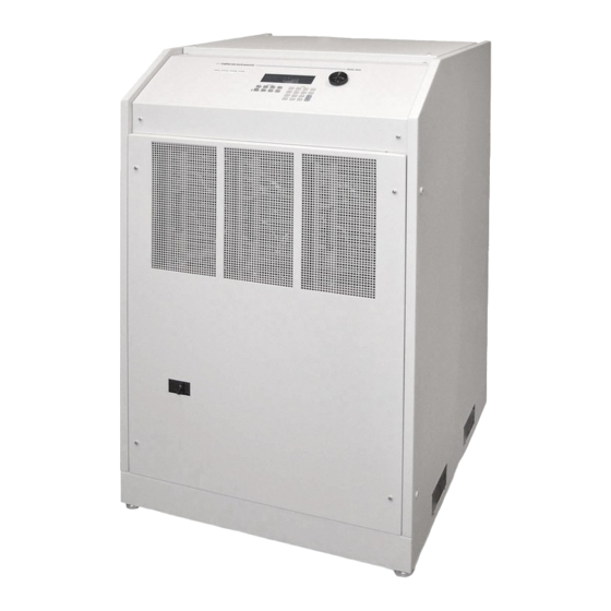
MX Series
AC and DC Power Source
Installation Manual
Contact Information
Telephone: 800 733 5427 (toll free in North America)
858 450 0085 (direct)
Fax: 858 458 0267
Email:
Domestic Sales: domorders.sd@ametek.com
International Sales: intlorders.sd@ametek.com
Customer Service: service.ppd@ametek.com
Web:
www.programmablepower.com
March 2011
Document No. 7003-968 Rev. D
Advertisement
Table of Contents

Related Manuals for Ametek MX Series


Summary of Contents for Ametek MX Series
- Page 1 MX Series AC and DC Power Source Installation Manual Contact Information Telephone: 800 733 5427 (toll free in North America) 858 450 0085 (direct) Fax: 858 458 0267 Email: Domestic Sales: domorders.sd@ametek.com International Sales: intlorders.sd@ametek.com Customer Service: service.ppd@ametek.com Web: www.programmablepower.com March 2011 Document No.
- Page 4 Installation Manual AC Power Source California Instruments Models: MX45-1 MX45-3 MX45-3Pi MX90-3 MX90-3Pi MX90-3Pi-MB MX135-3 MX135-3Pi MX135-3Pi-MB Rev C, June 2008.
- Page 5 About AMETEK AMETEK Programmable Power, Inc., a Division of AMETEK, Inc., is a global leader in the design and manufacture of precision, programmable power supplies for R&D, test and measurement, process control, power bus simulation and power conditioning applications across diverse industrial segments.
- Page 6 This page intentionally left blank.
- Page 7 Neither AMETEK Programmable Power Inc., San Diego, California, USA, nor any of the subsidiary sales organizations can accept any responsibility for personnel, material or inconsequential injury, loss or damage that results from improper use of the equipment and accessories.
- Page 8 AMETEK will, at its expense, deliver the repaired or replaced Product or parts to the Buyer. Any warranty of AMETEK will not apply if the Buyer is in default under the Purchase Order Agreement or where the Product or any part...
-
Page 9: Table Of Contents
Table 2-5: Analog Interface Connector ....................... 24 Table 2-6: BNC Connectors ..........................24 Table 2-7: External Sense Connector ......................... 25 Table 2-8: Clock and Lock Configuration settings ....................27 Table 2-9: Clock and Lock Initialization settings ....................28 MX Series... -
Page 10: Introduction
MX Series power sources with the programmable controller. All other MX Series manual are provided in Adobe Acrobat PDF format on CD ROM P/N CIC496. The CD ROM is included in the MX Series Shipkit. -
Page 11: Unpacking And Installation
Series unit(s) will be installed can support the weight of the unit(s). 2.2 Power Requirements The MX Series power Source has been designed to operate from a three-phase, three wire (Wye or Delta) AC input line. A protective earth connection is required as well. (PE). -
Page 12: Mechanical Installation
15 mins) before removing any cover.) See Figure 2-2 for details. No wiring for AC input connections is provided with the MX Series and must be provided by the end user or installer. Input wiring should be entered through the right hand side (when facing the back of the MX45, see Figure 2-4) wire access opening located at the rear bottom of the MX45 chassis. -
Page 13: Figure 2-2: Location Of Ac Input Fuse Block And Chassis Ground Connection
The front cover must be re- installed prior to use and the strain relief provisions located at the rear bottom of the unit must be used to maintain protection against hazardous conditions. MX Series... -
Page 14: Figure 2-3: Mx45 Ac Input Connection Diagram
Installation Manual - Rev D California Instruments 3ø AC Line Input PROTECTIVE GROUND EXTERNAL CIRCUIT BREAKER AC MAINS 3 PHASE Figure 2-3: MX45 AC Input Connection Diagram MX Series... -
Page 15: Ac On/Off Circuit Breaker On Mx45 Front Panel
If any MX45 system failure has occurred on any part of the MX45 system, AC input power must be removed immediately and not restored until the system has been inspected by a qualifier service technician. Always turn off the On/Off Circuit breaker before re-applying AC input power. MX Series... -
Page 16: Figure 2-4: Rear Panel
CAUTION: The AC input fuses can only be checked is the MX45 is completely de-energized and disconnected from any AC power input. Note: Under no circumstances should AC input power be applied if one or more of the AC input line fuses have failed and opened up. Figure 2-4: Rear Panel MX Series... -
Page 17: Output Connections
MX45 so it will not be necessary to power down the MX45 and remove the front covers. This can take the form of a panel-mounted socket (1 or 3 phase) of sufficient current and voltage rating. (Not supplied with MX45) MX Series... -
Page 18: Table 2-2: Suggested Output Wiring Sizes
Table 2-2: Suggested Output Wiring Sizes Load Current Wire Gauge (US) Circular Mils Metric (mm2) (kcmils) 65 AMPS 6 AWG 26.24 13.3 130 AMPS 4 AWG 41.74 21.1 260 AMPS 1/0 AWG 105.6 53.5 400 AMPS 2/0 AWG 133.1 67.4 MX Series... -
Page 19: Figure 2-6: Location Of Output Terminals
Connector Terminal Mode Output TB1A 3 Phase Phase A 3 Phase Phase B 3 Phase Phase C TB1B 1 Phase Phase A 1 and 3 Phase Neutral Table 2-3: Output Terminal connections. Figure 2-6: Location of Output Terminals MX Series... -
Page 20: Figure 2-7: Mx45-1 Output Wiring
Always disconnect all input power from the MX45 before removing the front panel cover that provides access to the input and output terminal connections. Route the wires from the back of the MX45 to the front in the provided cable guides. Figure 2-7: MX45-1 Output Wiring MX Series... -
Page 21: Figure 2-8: Mx45-3 Output Wiring
Always disconnect all input power from the MX45 before removing the front panel cover that provides access to the input and output terminal connections. Route the wires from the back of the MX45 to the front in the provided cable guides. Figure 2-8: MX45-3 Output Wiring MX Series... -
Page 22: Figure 2-9: Mx90 Or Mx90-Mb Output Wiring
EUT. These blocks are not enclosed however. Figure 2-9: MX90 or MX90-MB Output Wiring MX Series... -
Page 23: Figure 2-10: Two Mx45'S In Clock And Lock Mode Output Wiring
Installation Manual - Rev D California Instruments Figure 2-10: Two MX45's in Clock and Lock mode Output Wiring MX Series... -
Page 24: Figure 2-11: Mx135 Or Mx135-Mb Output Wiring
MX90 and MX135 systems are shipped with external output terminal blocks that enable the output wiring from two or three chassis to be combined, providing a single point of connection to the EUT. These blocks are not enclosed however. Figure 2-11: MX135 or MX135-MB Output Wiring MX Series... -
Page 25: Figure 2-12: Three Mx45'S In Clock And Lock Mode - Output Wiring
Installation Manual - Rev D California Instruments Figure 2-12: Three MX45's in Clock and Lock mode - Output Wiring MX Series... -
Page 26: Figure 2-13: Ship Kit Terminal Block Dimensions
The dimensions of the supplied terminal blocks are shown in Figure 2-13. Note that even if the EUT is a three-phase delta input, the output neutrals of the MX chassis' must be connected together for the system to work correctly. Figure 2-13: Ship kit Terminal Block dimensions MX Series... -
Page 27: Connectors - Rear Panel
Optional voltage range select. (-HV or -XV option) PARALLEL: Parallel operation control. INPUT ON: Input power status A ERR LO: Error Signal Phase A, low B ERR HI: Error Signal Phase B, high C ERR LO: Error Signal Phase C, Low MX Series... -
Page 28: Table 2-5: Analog Interface Connector
INPUT: Remote Inhibit. (Contact closure). INPUT: return. 2.7.3 BNC Connectors BNC connectors. Functions are called out on rear panel decal. Table shows connections from left to right when standing at the rear of the MX cabinet. Table 2-6: BNC Connectors MX Series... -
Page 29: Figure 2-14: Emergency Switch (Es Option) Shut Off Inter Connect On -Mb Systems
"Caution: BNC cable must be connected for system Emergency Shut-Down" See figure below for an illustration of a MX90-MB-ES interconnect. Figure 2-14: Emergency Switch (ES Option) shut off inter connect on -MB systems. MX Series... -
Page 30: Multiple Cabinet System Configurations
If the units being re-configured for multi-cabinet operation were not factory configured this way, it may be necessary to balance the amplifiers by adjusting their gain. Refer to MX Series User Manual (P/N 7003-960) for details on Amplifier balancing. When used as a multi-cabinet system, the system interface cables must be connected between the master and the auxiliary cabinets. -
Page 31: Clock And Lock Configurations
California Instruments 2.9 Clock and Lock Configurations The MX Series may optionally be equipped for clock and lock mode of operation. This mode is a special form of Master/Auxiliary which requires each chassis to have it's controller. As such, it is possible to create 2, 3, 6 or 9 phase power systems using 2 to 3 MX45 chassis. -
Page 32: Table 2-9: Clock And Lock Initialization Settings
To set up a GPIB remote controlled clock and lock systems, the GPIB addresses for the individual MX45's must be set to different address values in the UTILITY1, GPIB/RS232 SETUP screen. Note: This mode of operation is not supported by the MXGUI Windows software supplied with each MX45 unit. MX Series... -
Page 33: Basic Initial Functional Test
In the unlikely event the power source does not pass the functional test, refer to the calibration procedure in the MX Series User manual (P/N 7003-960) or call California Instrument’s customer satisfaction department for further assistance. -
Page 34: Figure 2-15: Functional Test Setup
Installation Manual - Rev D California Instruments 3ø Connect A, B or C AC Line Input Scope Power Resistor 15 kW Figure 2-16: Functional Test Setup. Index MX Series... - Page 35 ............14 Configuration ..........28 voltage drop DIP switch ............27 cables ............ 12, 15 voltage rating ............ 8 External Sync Clock/Lock ........... 29 Wire Sizes ..........12, 15 wiring input ............... 9 Functional Test ..........30 MX Series...
Need help?
Do you have a question about the MX Series and is the answer not in the manual?
Questions and answers