Advertisement
Available languages
Available languages
Quick Links
Advertisement

Related Manuals for Delta DVP02DA-E2


Summary of Contents for Delta DVP02DA-E2
- Page 1 DVP-0280230-01 20211108...
- Page 2 MOV instruction (Please refer to allocation of special registers D9900 ~ D9999). EN DVP02DA-E2 (DVP04DA-E2) is an OPEN-TYPE device. It should be installed in a control cabinet free of airborne dust, humidity, electric shock and vibration. To...
-
Page 3: Electrical Specifications
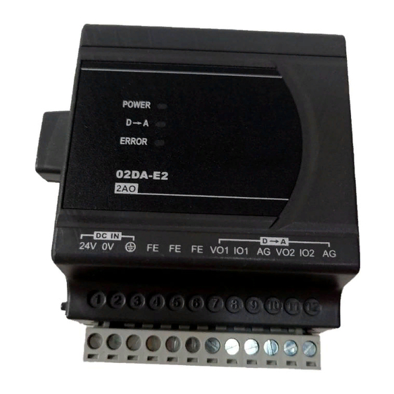
Note 3: Please connect power module terminal and analog output module terminal to system earth point and make system earth point be grounded or connects to machine cover. I/O Terminal Layout DVP02DA-E2 DVP02DA-E2 (2AO) DVP04DA-E2 DVP04DA-E2 (4AO) Electrical Specifications Digital/Analog module (02D/A &... -
Page 4: Functions Specifications
Control Register Attrib. Register name Explanation Set up by the system, model code: Model name DVP02DA-E2 = H’0041; DVP04DA-E2 = H’0081 Firmware version Display the current firmware version in hex. Output mode: Default = H’0000. O R/W CH1 output mode setting... - Page 5 Current output range: K0~K32,000. X R/W CH2 output signal value Default: K0. X R/W CH3 output signal value CR#18~CR#19 of DVP02DA-E2 are X R/W CH4 output signal value reserved. O R/W Adjusted Offset value of CH1 Set the adjusted Offset value of CH1 ~ CH4.
- Page 6 When DVP-ES2 MPU is connected with modules, registers D9900~D9999 will be reserved for storing values from modules. You can apply MOV instruction to operate values in D9900~D9999. When ES2 MPU is connected with DVP02DA-E2/DVP04DA-E2, the configuration of special registers is as below: Module...
- Page 7 Gain Offset Offset 16000 32000 Y=Voltage output, X=Digital input Equation for current output Mode1: 0.625μA = 20mA/32,000 ...
- Page 8 20mA Gain Current 12mA output +32767 -6400 +16000 +32000 Offset Digital input Mode 2 (CR#2 ~ CR#5) 4mA ~ +20mA,Gain = 12mA (19,200),Offset = 4mA (6,400) Range of digital data 0 ~ +32,000 Max./Min. range of digital data -6400 ~ +32,767 - 7 -...
- Page 9 ……………………………………………………………… 繁體中文 ………………………………………………………………………… 感謝您採用台達 DVP 系列產品。DVP02DA-E2 與 DVP04DA-E2 類比輸出模組接受來自 PLC 主機的 2 組與 4 組 16 位元數位資料,再將數位資料轉換為 2 點與 4 點類比信號輸出 (電壓或電流皆可)。並可透過主機以 FROM / TO 指令來讀寫模組內資料,或者以 MOV 指 令直接寫入對應通道的輸出值 (請參閱 D9900 ~ D9999 特殊暫存器使用說明)。 本安裝說明書提供給使用者電氣規格、功能規格、安裝配線之相關注意事項。其他詳 細之程式設計及指令說明請見 DVP-ES2 操作手冊【程式篇】 ,選購之周邊裝置詳細說...
- Page 10 註 1:類比輸出請與其他電源線隔離。 註 2:如果負載之輸入端漣波太大,造成配線受雜訊干擾時,請連接 0.1 ~ 0.47μF 25V 之電容。 註 3:請將電源模組之 端及 DA 類比信號輸出模組之 端連接到系統接地點,再將系統接 點作第三種接地或接到配電箱之機殼上。 輸入/輸出端子台配置 請參閱英文版頁碼 2 之端子配置圖,在此語言版本省略說明。 電氣規格 數位/類比模組 (02D/A & 04D/A) 24VDC (20.4VDC ~ 28.8VDC) (-15% ~ +20%) 電源電壓 02DA:1.5W,04DA:3W,由外部電源供應 額定最大消耗功率 脫落式歐式端子座 (端點距離:5mm) 連接方式 電壓輸出有短路保護但須注意長時間短路仍有可能造成內部線路損,...
- Page 11 屬性 暫存器名稱 說明 系統內定,機種代碼: 機種型號 DVP02DA-E2 = H’0041;DVP04DA-E2 = H’0081 16 進制,顯示目前韌體版本 韌體版本 輸出模式設定 : 出廠設定值為 H’0000 。 以 CH1 說明 : R/W CH1 輸出模式設定 模式 0 (H’0000):電壓輸出(10V). R/W CH2 輸出模式設定 模式 1 (H’0001):電流輸出 (0 ~ +20mA). R/W CH3 輸出模式設定...
- Page 12 過程影響其他模組的正常運作,建議每次只連接一台模組重置,並且於下達重置命令後等待 1 秒 再斷電。 特殊暫存器 D9900 ~ D9999 使用說明 DVP-ES2 主機連接特殊 I/O 模組時,暫存器 D9900 ~ D9999 將被佔用,使用者可利用 MOV 指令在程式中指定 D9900 ~ D9999 來運算。 DVP-ES2 主機連接 DVP02DA-E2/DVP04DA-E2 時,特殊暫存器的分配如下: 第 1 台 第 2 台 第 3 台 第 4 台...
- Page 13 電壓輸出 - 模式 0: 電 Gain 壓 輸 出 -32000 +32767 -32768 +16000 +32000 Offset 數值輸入 -10V 模式 0 (CR#2 ~ CR#5) -10V ~ +10V,Gain = 5V (16,000),Offset = 0V (0) -32,000 ~ +32,000 數位資料範圍 -32,768 ~ +32,767 數位資料範圍極限值 ...
- Page 14 ………………………………………………………………… 简体中文 …………………………………………………………………… 感谢您采用台达 DVP 系列产品。DVP02DA-E2 与 DVP04DA-E2 模拟量输出模块接受来 自 PLC 主机的 2 组与 4 组 16 位数字量数据,再将数字量数据转换为 2 点与 4 点模拟量 输出 (电压或电流皆可)。并可透过主机以 FROM / TO 指令来读写模块内数据,或者以 MOV 指令直接写入对应信道的输出值 (请参阅 D9900 ~ D9999 特殊寄存器使用说明)。 本安装说明书提供给使用者电气规格、功能规格、安装配线的相关注意事项。其它详 细的程序设计及指令说明请见 DVP-ES2 操作手册【程序篇】 ,选购的周边装置详细说...
- Page 15 总和精密度 1% 在 (0 ~ 55°C, 32 ~ 131°F) 范围内满刻度时 400μs / 每个通道 响应时间 16 位二补码 数字量数据格式 模拟量电路与数字量电路之间,透过光耦隔离,模拟量通道间未隔离 数字量电路与接地之间:500VDC 隔离方式 模拟量电路与接地之间:500VDC 模拟量电路与数字量电路之间:500VDC 24VDC 与接地之间:500VDC 控制寄存器 CR 属性 寄存器名称 说明 系统内定,机种代码: 机种型号 DVP02DA-E2 = H’0041;DVP04DA-E2 = H’0081 - 14 -...
- Page 16 电压输出设定范围 K-32,000 ~ K32,000。电流输出 R/W CH2 输出数值 设定范围 K0 ~ K32,000。出厂设定值为 K0。 R/W CH3 输出数值 DVP02DA-E2 之 CR#18~CR#19 为保留。 R/W CH4 输出数值 R/W CH1 微调 Offset 值 通道 CH1 ~ CH4 讯号的 Offset 设定, 出厂设定值为 R/W CH2 微调 Offset 值...
- Page 17 过程影响其他模块的正常运作,建议每次只连接一台模块重置,并且于下达重置命令后等待 1 秒 再断电。 特殊寄存器 D9900 ~ D9999 使用说明 DVP-ES2 主机连接特殊 I/O 模块时, 寄存器 D9900 ~ D9999 将被占用, 使用者可利用 MOV 指令在程序中指定 D9900 ~ D9999 来运算。 DVP-ES2 主机连接 DVP02DA-E2/DVP04DA-E2 时,特殊寄存器的分配如下: 第 1 台 第 2 台 第 3 台 第 4 台...
- Page 18 电压输出 - 模式 0: 电 Gain 压 输 出 -32000 +32767 +16000 +32000 -32768 Offset 数字输入 -10V 模式 0 (CR#2 ~ CR#5) -10V ~ +10V,Gain = 5V (16,000),Offset = 0V (0) -32,000 ~ +32,000 数字量数据范围 -32,768 ~ +32,767 数字量数据范围极限值 ...
Need help?
Do you have a question about the DVP02DA-E2 and is the answer not in the manual?
Questions and answers