Table of Contents
Advertisement
Quick Links
Operation and
Maintenance Manual
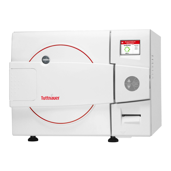
Electronic Laboratory Autoclaves
Models 2840 ELG-D
ELG-D: standard autoclave
C: optional system for fast cooling
PV: optional vacuum pump
BH: optional bio hazard filtration
F: optional fan for super-fast cooling
Cat. No. MAN205-0480000EN Rev. I
Tuttnauer Europe B.V.,
Hoeksteen 11 4815 PR P.O. Box 7191 4800 GD Breda,
The Netherlands Tel: 31 (0) 765423510, Fax: 31 (0) 765423540
Advertisement
Table of Contents

Related Manuals for Tuttnauer 2840 ELG-D


Summary of Contents for Tuttnauer 2840 ELG-D
- Page 1 Operation and Maintenance Manual Electronic Laboratory Autoclaves Models 2840 ELG-D ELG-D: standard autoclave C: optional system for fast cooling PV: optional vacuum pump BH: optional bio hazard filtration F: optional fan for super-fast cooling Cat. No. MAN205-0480000EN Rev. I Tuttnauer Europe B.V., Hoeksteen 11 4815 PR P.O.
- Page 2 ://tuttnauer.com/...
-
Page 3: Table Of Contents
Table of Contents Paragraph page no. General .....................4 1.1 Introduction ..................4 1.2 Incoming Inspection ................6 1.3 Warranty ...................6 1.4 Warranty Statement ................6 1.5 Accessories ..................7 Safety Instructions..................8 Technical Data ..................10 3.1 Storage Conditions................10 3.2 Operating Conditions ..............10 3.3 Directives and Standards ..............11 3.4 Electrical Data.................11 3.5 Environment Emission Information ..........11 3.6 Water Quality ..................11... - Page 4 5.7 Program 7: Waste (PV – pre-vacuum models only) ......35 5.8 Program 8: Hollow Load (PV – pre-vacuum models only)....36 5.9 Program 9: Bio Hazard 1 (BH, bio-hazard models only) ....37 5.10 Program 10: Bio Hazard 2 (BH, bio-hazard models only) ....38 5.11 Program 11: Bio Hazard Liquids (BH, bio-hazard models only) ..39 5.12 Program 12: Vacuum Test (PV, pre-vacuum models only) ....40 5.13 Program 13: Bowie and Dick Test (PV –...
- Page 5 11.5 Changing parameters..............74 11.6 System Parameters.................75 11.7 Maintenance ...................76 11.8 Cycle parameters ................77 Service and Maintenance Instructions .............79 12.1 Preventive and Scheduled Maintenance .........79 12.2 Draining the Reservoirs..............80 12.3 Cleaning the Air Jet.................82 12.4 Replacing the Door Gasket .............82 12.5 Checking the Safety Valve ..............83 12.6 Cleaning the water outlet strainer ............85 12.7 Water Sensor Cleaning ..............86 Troubleshooting ..................88...
-
Page 6: General
1 General Read the Operating Instructions carefully, before beginning any operation on the autoclave! 1.1 Introduction Model 2840 ELCPVG is a laboratory sterilizer designed especially for the sterilization of instruments, liquids, and other materials in hospital laboratories, medical laboratories, research institutes, food laboratories and pharmaceutical facilities. - Page 7 The temperature and pressure are controlled through sensors placed inside and outside the media container or bottles. The sterilizer is fully automatic with a choice of 10 programs, eliminating any need for operator intervention during a cycle (program 7-10 are for vacuum test only). A computerized control unit enables precise control and monitoring of physical parameters and clear documentation of the sterilization cycles.
-
Page 8: Incoming Inspection
All Tuttnauer products are carefully inspected prior to shipment and all reasonable precautions are taken in preparing them for shipment to assure safe arrival at their destination. -
Page 9: Accessories
All transportation charges must be paid both ways by the owner. This warranty will be void if the unit is not purchased from an authorized full service Tuttnauer dealer. 1.5 Accessories Basket accessories: A set of two baskets is available for the unit. The baskets are made of stainless steel wire and have a handle. -
Page 10: Safety Instructions
2 Safety Instructions The autoclave has unique characteristics. Please read and understand the operation instructions before first operation of the autoclave. The following issues may require instructions guidance provided by the manufacturer: how to operate the autoclave, the door safety mechanism, the dangers involved in circumventing safety means, how to ensure that the door is closed, and how to select a correct sterilization program. - Page 11 Open the door slowly to allow steam to escape and wait 5 minutes before you remove the load. When sterilizing liquids, wait 10 minutes. Once a month, ensure that the safety valves are functioning, and once annually a certified tester must conduct pressure chamber safety tests.
-
Page 12: Technical Data
3 Technical Data 3.1 Storage Conditions Packed or unpacked, autoclave shall be retained in indoor conditions! 3.2 Operating Conditions This device is for indoor use only! The sterilizer should be loaded only with autoclavable material! The environment shall not exceed an ambient temperature of 40ºC ... -
Page 13: Directives And Standards
13485:2012 (Quality Systems for Medical Devices) 9001:2008 (Quality Systems) 93/42/EEC (Medical Device Directive) Tuttnauer. Ltd. company also works in conjunction with and refers to: AAMI/ANSI-ST8 Hospital sterilizers ASME American Society of Mechanical Engineers Section VIII, Division 1, for unfired pressure vessels... - Page 14 The distilled or mineral-free water supply shall be according to the table below: Physical Characteristics and Maximum acceptable contaminants levels in water or steam, for steam generator and sterilizers Contaminants in Contaminants in water supplied to condensate at steam generator/chamber inlet to sterilizer Evaporate residue ≤...
-
Page 15: Specifications
Hardness: 0.7 - 0.2 mmol/l. Water temperature shall not exceed 15°C (59°F). 3.7 Specifications Property Value Height 440mm Overall Width 530mm dimensions Length 760mm Maximum dimensions Width 1090mm (door open) Distance Width 315mm (front legs), 400mm (rear legs) between supporting Length... -
Page 16: Overall Dimensions
3.8 Overall Dimensions 3.9 Electrical Data Property Value Total Power 3000W Voltage 230VAC / 1 ph Amperage Protection against electrical Class I (IEC 60601-1) shock Mains supply fluctuation +/- 10% Degree of protection by IP31 enclosure Note: In order to avoid any injury by electrical hazard, it is recommended that a ground fault protection device be installed in the electrical panel feeding the autoclave (local codes may make this mandatory). -
Page 17: Utilities
3.10 Utilities Specifications Value Mineral free water See table in sec. 3.9. Power supply * 1 phase, 230VAC ±10%, 60Hz Recommended circuit breaker Compressed Air (PV- re-vacuum models 1/2" 3 Bar (44-58 psi) only) Tap water 1/2", 2-6 Bar (29-44 psi) Mineral free water 1/2", 2-3 Bar (29-44 psi) 2"... -
Page 18: Safety Features
Ready” is door only) Displayed = 10 sec. Don’t Touch LAB048-0462 On the door frame Microswitches behind the door please Contact cover Tuttnauer Service Don’t Touch LAB048-0463 On the door frame Microswitches behind the door please Contact cover Tuttnauer Service... - Page 19 On-Off LAB048-0018 Near the Power switch Page 17...
-
Page 20: Front View
3.15 Front View Description Description Main switch circuit Door switch breaker Operating keyboard Door closing device Printer cover Water reservoir funnel Rear Leg Water level gauge Printer (option) Autoclave cover Page 18... -
Page 21: Rear View
USB connection Display Mineral-free water reservoir Front Legs cover Mineral-free water Safety valve reservoir drain valve Door cover 3.16 Rear View Description Description Water reservoir cover Tap water inlet Compressed air inlet Overflow drain Compressed air pressure gauge Chamber water strainer Main power electrical cable Air pressure regulator socket... -
Page 22: Control Panel
4 Control Panel 4.1 Control Panel Drawing Description Display Keypad: Up Button Keypad: Start/Stop Button Keypad: Down Button Printer Page 20... -
Page 23: Description And Functions Of The Front Panel Keyboard
4.2 Description and Functions of the Front Panel Keyboard The front panel is composed of 3 sections: Display screen. Keypad. Printer 4.2.1 Display screen The display is a LCD panel used to display the current status of the autoclave while using Operational Messages and Error Messages. ... -
Page 24: Displayed Error Messages / Symbols
When adjusting a parameter and the cursor is blinking on “SET” or “EXIT” the UP ▲ key activates that procedure.” DOWN key This key has the following functions: In the menu directories: This key enables the operator to browse through the cycles. In the directories available: ... -
Page 25: Displayed Operational Messages / Symbols
4.4 Displayed operational messages / Symbols Message / Message / Symbol Symbol Required Action Description Name This symbol is displayed when the Close the door. door is open. Door is This message is open Close the door to perform a new displayed when the (during cycle. -
Page 26: Description Of Operation
4.5 Description of Operation 4.5.1 Air removal The PV (pre-vacuum) models are equipped with a vacuum pump for performing the air removal stage. Before the sterilization stage, one or two vacuum pulses (according to the cycle) are built in the chamber. Removing air pockets in the autoclaved material improves the penetration of the steam during the sterilization stage. -
Page 27: Leakage Test - Optional For Pv (Pre-Vacuum) Models Only
4.5.5 Exhaust When the timed sterilization cycle is complete, the unit enters into the exhaust stage, provided that a program other than the liquid program was selected. The steam is exhausted from the chamber, bringing the internal pressure down to atmospheric pressure. Note: In the Bio-Hazard cycles (optional for BH, bio-hazard models), all exhausts from the chamber before completion of the Sterilization phase are performed through the bio-hazard filter. -
Page 28: Sterilization Programs
5 Sterilization Programs Sterilization Programs models models models only only only Temp. Icon Name 134°C Glass (273F) 121°C Plastic (250F) 121°C Liquid A (250F) 121°C Liquid B – Waste* (250F) √ Liquid A 121°C – (250F) Cooling* √ Liquid B 121°C Waste (250F) - Page 29 √ Hazard (273F) √ Hazard (250F) √ Hazard (250F) Liquids* √ Vacuum test (PV only)* √ 134°C Bowie 3.5 1 and Dick* (273F) 80 °C Warm- 176F) 80 °C Isotherm 176F) 121C Mixture* (250F) Glass 121C Test* (250F) 121C Durham* (250F) *These programs are optional During the process, the stages of the cycle will be displayed on the...
- Page 30 The stages names are as follows: Start Pulse Low (PV models only) Pulse High (PV models only) Heating Sterilization Cooling (C models only) Exhaust Drying (PV model only) Ending Page 28...
-
Page 31: Program 1: Glass
5.1 Program 1: Glass glass instruments, when manufacturer recommends autoclaving at temperatures of 134C (273F). Drying stage is available for PV (pre-vacuum) models only. Nominal parameters default settings Sterilization temperature: 134C (273F). Sterilization time: 3 minutes. Drying time: 1 minute. (PV – pre-vacuum models only). Operations sequence: (PV, pre-vacuum models only) Pulse low/Pulse high: at one ... -
Page 32: Program 2: Plastic
5.2 Program 2: Plastic For plastic and other delicate instruments, when the manufacturer recommends autoclaving at temperatures of 121C (250F). Drying stage is available for PV (pre-vacuum) models only. Nominal parameters default settings Sterilization temperature: 121C (250F) Sterilization time: 15 minutes ... -
Page 33: Program 3: Liquid A
5.3 Program 3: Liquid A For liquids when the manufacturer recommends autoclaving at temperatures of 121C (250F) for 15 minutes. Cautions! Both PT100 temperature sensors must be inside the bottles. For proper sterilization, fill the bottles with approximately the same amount of liquid. Nominal parameters default settings ... -
Page 34: Program 4: Liquid B - Waste
5.4 Program 4: Liquid B – Waste For liquids when the manufacturer recommends autoclaving at temperatures of 121C (250F) for 30 minutes, such as liquid waste. Cautions! Both PT100 temperature sensors must be inside the bottles. For proper sterilization, fill the bottles with approximately the same amount of liquid. -
Page 35: Program 5: Liquid A - Cooling (C - Cooling Models Only)
5.5 Program 5: Liquid A – Cooling (C – cooling models only) For liquids when the manufacturer recommends autoclaving at temperatures of 121ºC (250F). for 15 minutes. Cautions! Both PT100 temperature sensors must be inside the bottles. For proper sterilization, fill the bottles with approximately the same amount of liquid. -
Page 36: Program 6: Liquid B - Waste Cooling (C - Cooling Models Only)
5.6 Program 6: Liquid B – Waste Cooling (C – cooling models only) For liquids when the manufacturer recommends autoclaving at temperatures of 121ºC (250F) for 30 minutes, such as liquid waste. Cautions! Both PT100 temperature sensors must be inside the bottles. For proper sterilization, fill the bottles with approximately the same amount of liquid. -
Page 37: Program 7: Waste (Pv - Pre-Vacuum Models Only)
5.7 Program 7: Waste (PV – pre-vacuum models only) For waste products when the manufacturer recommends autoclaving at temperatures of 134C (273F). Nominal parameters default settings Sterilization temperature: 134C (273F) Sterilization time: 7 minutes Drying time: 15 minutes. Operations sequence: ... -
Page 38: Program 8: Hollow Load (Pv - Pre-Vacuum Models Only)
5.8 Program 8: Hollow Load (PV – pre-vacuum models only) For class B sterilization of pipes and wrapped pipes, double wraps, when the manufacturer recommends autoclaving at temperatures of 121C (250F). Nominal parameters default settings Sterilization temperature: 121C (250F) ... -
Page 39: Program 9: Bio Hazard 1 (Bh, Bio-Hazard Models Only)
5.9 Program 9: Bio Hazard 1 (BH, bio-hazard models only) All exhaust from the chamber before completion of the Sterilization stage is performed through the bio-hazard filter. For instruments, when the manufacturer recommends autoclaving at temperatures of 134C (273F) for 30 minutes. Drying stage is available for PV (pre-vacuum) models only. -
Page 40: Program 10: Bio Hazard 2 (Bh, Bio-Hazard Models Only)
Ending: The system checks that End temperature and End pressure have been reached, and then releases the door. 5.10 Program 10: Bio Hazard 2 (BH, bio-hazard models only) All exhaust from the chamber before completion of the Sterilization stage is performed through the bio-hazard filter. For instruments, when the manufacturer recommends autoclaving at temperatures of 121C (250F) for 45 minutes. -
Page 41: Program 11: Bio Hazard Liquids (Bh, Bio-Hazard Models Only)
Ending: The system checks that End temperature and End pressure have been reached, and then releases the door. 5.11 Program 11: Bio Hazard Liquids (BH, bio-hazard models only) All exhaust from the chamber before completion of the Sterilization stage is performed through the bio-hazard filter. For liquids when manufacturer... -
Page 42: Program 12: Vacuum Test (Pv, Pre-Vacuum Models Only)
Slow Exhaust: Steam is exhausted from the chamber at a slow rate, until it reaches the pressure of 30 kPa above the ambient pressure. Then steam is exhausted out of the chamber at a fast rate until pressure decreases to ambient pressure. Note: If the cycle fails, fast exhaust is performed through the bio-hazard filter. -
Page 43: Program 13: Bowie And Dick Test (Pv - Pre-Vacuum Models Only)
5.13 Program 13: Bowie and Dick Test (PV – pre-vacuum models only) Bowie and Dick test is a test program with the following parameters: Nominal parameters default settings Sterilization temperature: 134ºC (273º F) Sterilization time: 3.5 minutes. Drying time: 1 minute. -
Page 44: Program 14: Warm-Up
5.14 Program 14: Warm-Up Pre-warming the chamber at 80C (176F) without drying. Caution! This is not a sterilization program! Nominal parameters default settings Warm-up temperature: 80 C ( 176 F). Warm-up time: 20 minutes. Operations sequence: Pulse low/Pulse high: N/A ... -
Page 45: Program 15: Isothermal
5.15 Program 15: Isothermal For liquids when the manufacturer recommends autoclaving at 60- 100C (140-212F) with no drying. Recommending for melting of agar, pasteurization etc. Caution! This is not a sterilization program! Put one PT100 inside the bottle, leave the second one hanging in the chamber outside the bottle (see below). -
Page 46: Program 16: Air Mixture
Cooling: N/A. Fast Exhaust: the steam is exhausted out of the chamber at a fast rate until pressure decreases to ambient pressure. Drying: N/A Ending: The system checks that End temperature and End pressure have been reached, and then releases the door. Note: Some water may remain in the chamber. -
Page 47: Program 17: Glass Test
needed to prevent swelling or warping of soft plastic items. Chamber fan is used to mix air with steam. Sterilization: Sterilization is controlled in a way that the sterilization pressure remains approx. 30% above the theoretical pressure corresponding to the same temperature according to the steam table. Cooling: Forced cooling to the required end temperature, chamber ... -
Page 48: Program 18: Durham
per minute. This will make the last stage of the heating take approximately 21 minutes. This is to check the durability of the bottles. Sterilization: Sterilization temperature is maintained constant during the sterilization time. Cooling: Forced cooling to the required end temperature, chamber ... - Page 49 (PV, pre-vacuum models only) Pulse low/Pulse high: at one pulse it will build vacuum down to 25 kPa. Heating: Steam enters the chamber and heats it up until the sterilization temperature is reached. Sterilization: Sterilization temperature is maintained constant during ...
-
Page 50: Screens
6 Screens 6.1 Screens following a completely successful cycle – "Cycle Ended" 1. System Ready 2. Pulse Low (PV 3. Pulse High (1/1) model only) (PV model only) 5. Heating 6. Sterilization 7. Exhaust 8. Drying (PV model 9. Ending 10. -
Page 51: Screens Following Aborted Cycles After Complete Sterilization Stage
6.2 Screens following aborted cycles after complete sterilization stage The sterilization phase ended successfully – cycle ended and the reason of failure is displayed For example the next two scenarios: 6.2.1 Canceled by user after complete sterilization stage The cycle ended successfully, the reason for aborted cycle is displayed. - Page 52 6.3.2 Failure according to Cancellation by user before complete sterilization stage When "Cycle Failed" appears on the screen, the user shall press START/STOP key in order to delete the "Cycle Failed" message An example for all displayed warnings according to Cycle Failed: Cycle Failed message Reason of failure...
-
Page 53: Printer
7 Printer 7.1 Printer Output The printing is on thermal paper with 24 characters per line and contains the following information: Date: Time: Ser. Num: Model: Version: Cycle Num: Cycle: Ster Temp: ... - Page 54 CLK 1: 12:12:10:00 two clocks The time, temperature and pressure during S 00:22:07 134.5 311.6 sterilization The time, temperature and pressure during S 00:22:06 134.5 311.6 sterilization The time, temperature and pressure during S 00:21:06 134.6 311.0 sterilization The time, temperature and pressure during S 00:20:06 134.5 310.1...
-
Page 55: Printer Handling
Date: 9/FEB/2010 Date sterilization cycle started ----------------------- Time: 08:51:39 Time of turning on Date: 9/FEB/2010 Date of turning on POWER ON The device is turned on Time: 00:00:00 Time of turning off Date: 9/FEB/2010 Date of turning off POWER OFF The device is turned off Legend Insert Water... - Page 56 Fig. 2 Press the OPEN key to open the printer cover as shown (see Fig. 3/1). Handle the paper cutter carefully not to cut your hand. Place the paper roll making sure it unrolls in the proper direction as shown (see Fig. 3/2). Take out the paper and re-close the cover as shown (see Fig.
- Page 57 Cautions! Never disassemble the printer. Failure to follow this instruction may cause overheating or burning of the printer or the AC adapter. Or an electric shock, which may lead to fires or accidents. Never use the printer in a place of extreme humidity or any place where it can possibly be splashed by any liquids.
-
Page 58: Installation
8 Installation 8.1 Placing Cautions! The sterilizer is not portable or hand-held equipment; it is a fixed device so it is forbidden to move it. The sterilizer must be placed on a rigid and leveled surface. The stand must be able to withstand the load of the device and loaded material. -
Page 59: Preparation Before Sterilization
9 Preparation Before Sterilization The purpose of packaging and wrapping of items for sterilization is to provide an effective barrier against sources of potential contamination in order to maintain sterility and to permit aseptic removal of the contents of the pack. Packaging and wrapping materials should permit the removal of air from the pack, penetration of the sterilizing water vapor into the pack and removal of the sterilizing vapor. -
Page 60: Wrapped Instruments
Wrapped instruments should be packed in material that promotes drying such as autoclave bag, autoclave paper, and muslin towels. It is highly recommended to utilize the Tuttnauer Pouch Rack. This rack allows the operator to place pouches on their side, thus increasing the capacity of the autoclave significantly and promoting better drying of the instruments. -
Page 61: Packs
9.3 Packs Place packs upright on the tray, side by side. Packs should not touch the chamber walls. Pack instrument sets in a manner that prevents damage to delicate items. Pack hollowware sets so that all openings face the same direction and so that the contents cannot move inside the pack. -
Page 62: Tubing
9.4 Tubing When placing in a tray, Make sure that both ends are open, without sharp bends or twists. Right Wrong 9.5 Liquids Use only heat-proof glass, filled 2/3 full. Ensure that the glass container is covered but not sealed to prevent pressure build-up. -
Page 63: Operating Instructions
10 Operating Instructions 10.1 Turning on the autoclave To start the system, turn on the main switch (1), located on the right side of the autoclave. 10.2 Opening the door Place your thumb on the plastic door cover (1) and the other fingers in the handle (3). -
Page 64: Operations
Compatible material Proper weight. 10.4 Operations Select the program. UP key: next program. DOWN key: previous program. Attention: Selecting a program is possible only when the door is open. Verify that you chose the required cycle. If the autoclave is equipped with a printer verify that a paper roll is inserted in the printer. -
Page 65: Unloading
0000 is displayed on the screen with the cursor blinking on the right digit. To increase or decrease the digits, press the UP or DOWN keys. Set your password, then move the cursor to Set by pressing the START/STOP key. When Set is blinking, press the UP or DOWN keys to return to the program screen. -
Page 66: Stopping The Process And Canceling The Error Message
Wear heat-resistant gloves or use the tray handle to remove the load from the autoclave On completion of the cycle, the load shall be visually inspected to ascertain that the load is dry, and that sterilization indicators have made the required color change. -
Page 67: Loading And Unloading The Device
10.9 Loading and Unloading the Device 10.9.1 Safety Protective equipment and clothes and other safety instructions should be implemented in accordance with local and national regulations and/or rules! For proper sterilization, do not overload the chamber. Only autoclavable products shall be used; please refer to the manufacturer instructions for sterilization of unknown materials or instruments. -
Page 68: Checking And Changing Parameters And Other Data
11 Checking and Changing Parameters and Other Data Bacsoft control panel allows changing parameters of the cycle and of the system, exporting various data to, and importing from, a USB device or to the printer, and some other options. Cycle parameters are changeable for Custom programs only (see Duplicate cycles), with the exception of the Temperature sensors, Displayed inputs, and Dry Time. -
Page 69: Changing A Parameter
Note: To exit every screen and to return to the previous screen (to get one level up): move the cursor to Exit by pressing the UP or DOWN keys and then press the Start/Stop key. - or- press the UP and DOWN keys simultaneously. ... - Page 70 Note: Please note the maximum and minimum values for this parameter shown on the screen. Your value must be within these boundaries. Below is the example of changing the Dry time parameter on the screen used in the previous section: Page 68...
-
Page 71: Quick Options Screen
Note: To exit every screen and to return to the previous screen: move the cursor to Exit by pressing the UP or DOWN keys and then press the Start/Stop key - or- press the UP and DOWN keys simultaneously 11.3 Quick options screen When the autoclave is on and no cycle is running, press Up and Down keys simultaneously to enter the Quick options screen. - Page 72 Below you can find instructions how to login and enter the Main menu. Section 11.1 above explains how to browse through the menus; section 11.2 explains how to change a parameter. Below is the explanation of some Quick Options. 11.3.1 Version Information This directory allows viewing information of the current, factory default, and previous software versions.
- Page 73 On the Start cycle by clock screen, the time is displayed in the form “HH:MM”. The hour range is 24 hours (i.e. from "0" to "24"). Setting the time to start the cycle Move the cursor to the Time field. Set the required time .
- Page 74 Disabling the START CYCLE BY CLOCK On the Start Cycle by Clock screen, move the cursor to Disabled. Press Up or Down key to disable Starting cycle by clock. Exit the Enabling the Start Cycle by Clock. 11.3.3 Set date and time This subdirectory enables the operator to set date and time.
-
Page 75: Logging In And Entering The Main Menu
Caution! After setting time and date, turn the autoclave off and then on again. 11.4 Logging in and entering the Main menu Below you can find instructions how to login and enter the Main menu. Section 11.1 above explains how to browse through the menus, section 11.2 explains how to change a parameter. -
Page 76: Changing Parameters
0000 is displayed on the screen with the cursor flashing on the right digit. Set the code to 0001. You will get to the Main menu. Below is the list and the explanation of some options available to user on the Main Menu. -
Page 77: System Parameters
11.6 System Parameters This menu is listing the system parameters that are the same for all cycles. Browse to the following folder: Main menu\System parameters You will see the following screen: 11.6.1 Screen Saver In this menu you can define the screensaver delay time, i. e. how long the keyboard will be untouched before the screensaver activates. -
Page 78: Maintenance
11.7 Maintenance Maintenance procedures provided by Bacsoft software allow you additional tests and USB input/output options. Browse to the following folder: Main menu\Maintenance You will see the following screen listing the maintenance options: Below is the instruction for autoclave’s maintenance menu. 11.7.1 Reset atmospheric pressure In this menu you can reset the atmospheric pressure value. -
Page 79: Cycle Parameters
11.7.2 Printer test In this menu you can check the normal function of the printer. The printer will print the list of errors. Browse to the following folder: Maintenance\Printer test The following screen will appear to confirm that the test has been done. See the printout shown in the Printer handling chapter of the user manual. - Page 80 parameters on your screen). For the custom cycles created by duplication, and for the Warm Up cycle, more options are changeable. Operator is not allowed to create custom cycles; only authorized technician can do this. 11.8.1 Dry Time This parameter defines duration of the drying stage for the cycle. Browse to the following folder: Cycle parameters\Drying\Dry Time Change the parameter as desired.
-
Page 81: Service And Maintenance Instructions
12 Service and Maintenance Instructions 12.1 Preventive and Scheduled Maintenance The maintenance operations described in this chapter have to be fulfilled periodically to keep the device in good condition and to reduce the breakdown time to a minimum. The user can easily execute these operations in accordance with further instructions. -
Page 82: Draining The Reservoirs
12.1.3 Periodically By the operator Once a month, activate the safety valve (see sec. 12.5). Once a month clean the strainer as per sec. 12.6. Cleaning frequency may be reduced according to experience. Check the door gasket every 12 months and replace it if required (see sec. - Page 83 If the autoclave is equipped with automatic mineral-free water supply, this instruction applies to the clean-water reservoir only. In this case close the mineral-free water supply valve before draining the reservoir. To drain the reservoir, use item (5) with the plastic hose (6) attached to it (supplied with the autoclave).
-
Page 84: Cleaning The Air Jet
12.3 Cleaning the Air Jet (Located in the water reservoir.) A dirty air jet is the number one cause of failed spore tests The elimination of air from the sterilization chamber during heat up is critical to the proper operation of the autoclave. Failure of the air removal system will be responsible for incomplete sterilization, indicator strips that do not turn, failed spore tests and aborted sterilization cycles. -
Page 85: Checking The Safety Valve
Pull off the gasket from the door groove and install the new gasket referring to the drawings as above points 1, 2 and 3. Caution! See drawing below for the right direction of the gasket. 12.5 Checking the Safety Valve Both safety valves, the chamber safety valve (2) and the generator safety valve (3), are located on the top rear of the autoclave (see Rear View). - Page 86 ASME-approved type safety valve Description water reservoir cover Safety valve Pulling device Pressure relief ring Page 84...
-
Page 87: Cleaning The Water Outlet Strainer
PED-approved type safety valve Description Water reservoir cover Safety valve Pressure relief nut 12.6 Cleaning the water outlet strainer Caution! Before proceeding, Make sure that the electric cord is disconnected and there is no pressure or water in the chamber. Warnings! The strainer’s cover is HOT Do not touch the strainer’s cap, mounted on the exhaust line,... -
Page 88: Water Sensor Cleaning
Water Strainer Strainer Strainer Gasket element Housing 12.7 Water Sensor Cleaning It is required that the water sensor be cleaned at least once per week. Cleaning the sensor will ensure that the water level in the chamber is properly reported to the microprocessor all during the cycle. The water sensor is located in the rear of the chamber. - Page 89 Page 87...
-
Page 90: Troubleshooting
13 Troubleshooting Only technical personnel having proper qualifications and holding technical documentation (including a technician manual) and adequate information are authorized to service the apparatus. Problem/ Error Message / Symbol Description Corrective Action Message Turn the main switch on. The main switch is in the ‘off position. Make sure the power cord is The power cord is not connected properly connected to the... - Page 91 Problem/ Error Message / Symbol Description Corrective Action Message is disconnected (both while cycle is connected" running or not). This message is displayed if the temperature drops for more than 1 "Low Temp" Perform a new cycle. second below the sterilization temperature during sterilization cycle.
- Page 92 Problem/ Error Message / Symbol Description Corrective Action Message "RTC Error - Please Set Set Current Date And Time. This message is displayed in order Current If the problem persists, call to set the date and the time. Date and the technician.
- Page 93 Problem/ Error Message / Symbol Description Corrective Action Message printer after the autoclave turns on). condition) and perform a new cycle. check and fix the mineral free water supply. This message is displayed if the 2.check and clean the water "No Water"...
- Page 94 BASKETS AND CONTAINERS Container for waste products Basket Stainless steel container Stainless steel wire baskets for waste products L x D x H (mm) Capacity L x D x H (mm) Capacity 400 x 180 x 160 400 x 190 x 160 Pouch Rack ACS215-0008 Page 92...
-
Page 95: Spare Parts List
14 Spare Parts List Part number Description FIL175-0042 Filter, Air, 0.2 Micron, Model 50mm D Thermal paper for CUSTOM PLUSII THE002-0066 printer roll 57mm, d=50mm 15 Accessories Part number Description GAS084-0007 Drain P.V.C. Tube, 8x12 THE002-0052 Printer, PLUSII-S2B-0004 Cable, Electric, Plug + Socket /230V 10A, WIR040-0002 Page 93...
Need help?
Do you have a question about the 2840 ELG-D and is the answer not in the manual?
Questions and answers