Table of Contents
Advertisement
Quick Links
Advertisement
Table of Contents

Subscribe to Our Youtube Channel
Related Manuals for Tuttnauer 2840 EL-D


Summary of Contents for Tuttnauer 2840 EL-D
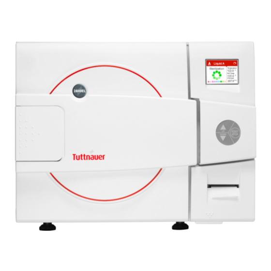
- Page 1 OPERATION & MAINTENANCE MANUAL Electronic Table top Autoclave (with cooling option) Model 2840 EL-D Cat. No. MAN205-0450001EN Rev A + Tuttnauer Europe b.v., Hoeksteen 11, 4815 PR, Breda, P.O. Box 7191, 4800 GD Breda, Netherlands. )+31/76-5423510, 0Fax: +31/76-5423540, E-mail: info@tuttnauer.nl...
-
Page 2: Table Of Contents
TABLE OF CONTENTS PARAGRAPH PAGE NO. GENERAL ........................5 Incoming Inspection ...................5 Warranty .......................5 Warranty Statement ....................5 SAFETY INSTRUCTIONS..................7 TECHNICAL DATA .....................9 Introduction......................9 Storage Conditions ................... 10 Operating Conditions ..................10 Specifications ....................11 Electrical Data ....................12 Utilities ....................... 13 Environment Emission Information .............. - Page 3 PRINTER ........................30 Printer Output ....................30 Printer Handling ....................32 INSTALLATION ......................35 Placing ....................... 35 Lifting and carrying ..................35 Filling the Mineral-Free Water Reservoir............ 36 PREPARATION BEFORE STERILIZATION............38 10.1 Instruments ....................... 38 10.2 Tubing ........................ 40 10.3 Liquids........................
- Page 4 TROUBLESHOOTING ..................... 73 SPARE PARTS LIST ....................77 ACCESSORIES ......................77 Page 3 of 77...
- Page 5 TABLE OF CONTENT (Cont.) DRAWINGS PAGE NO. FRONT VIEW ........................17 REAR VIEW ......................... 18 Page 4 of 77...
-
Page 6: General
If damage is apparent, contact your dealer or point of purchase, so that they may notify the manufacturer and file a claim with the appropriate carrier. All Tuttnauer products are carefully inspected prior to shipment and all reasonable precautions are taken in preparing them for shipment to assure safe arrival at their destination. - Page 7 No autoclaves will be accepted for repair without proper authorization from us. All transportation charges must be paid both ways by the owner. This warranty will be void if the unit is not purchased from an authorized full service Tuttnauer dealer. Page 6 of 77...
-
Page 8: Safety Instructions
SAFETY INSTRUCTIONS The autoclave has unique characteristics. Please read and understand the operation instructions before first operation of the autoclave. The following issues may require instructions guidance provided by the manufacturer: how to operate the autoclave, the door safety mechanism, the dangers involved in circumventing safety means, how to ensure that the door is closed, and how to select a correct sterilization program. - Page 9 Once annually, or more frequently, effective tests must be performed, i.e., calibration and validation. Examine the condition of assemblies on a regular basis. Make sure there are no leaks, breaks, blockages, whistles or strange noises. It is required to conduct maintenance operations as instructed. Immediately notify the person in charge of any deviation or risk for the proper function of the device.
-
Page 10: Technical Data
TECHNICAL DATA Introduction Model 2840 ELC is a table-top sterilizer designed especially for the sterilization of instruments, liquids, and other materials in hospital laboratories, medical laboratories, research institutes, food laboratories and pharmaceutical facilities. A computerized control unit ensuring a fully automatic sterilization cycle controls the autoclave. -
Page 11: Storage Conditions
Storage Conditions The packed or unpacked autoclave shall be retained in indoor conditions! Operating Conditions This device is for indoor use only! The sterilizer should be loaded only with autoclavable material! The environment shall not exceed an ambient temperature of 40ºC and a relative humidity of 85% respectively. -
Page 12: Specifications
Specifications Property Value Dia. 280 mm (11 ) Chamber Depth 504 mm (19.8 ) Chamber volume 28.5 lit. (7.5 US gal) Width 530 mm (20.8 ) Height External dimensions 444 mm (17.4 ) Length 605 mm (23.8 ) Maximum dimensions (door 950 mm (37 ) open) Distance between... -
Page 13: Electrical Data
Property Value Width 63 cm (24.8 ) Shipping Height 71 cm (28.0 ) dimension Length 80 cm (35.8 ) Volume 0.36 m3 (14.5 ft³) Max. water Mineral- 5 lit. (1.1 US gal) volume free water Min. water 1.5 lit. (0.4 US gal) reservoir volume Maximum dimensions... -
Page 14: Utilities
Utilities Specifications Value Mineral free water See table in sec. 3.9. * 1 phase, 208/230VAC ±10%, 60Hz Power supply Recommended circuit breaker * According to the local network. Attention: · A switch or circuit-breaker must be included in the building installation. This switch or circuit-breaker shall be in close proximity to the equipment, within easy reach of the operator;... -
Page 15: Safety Features
3.10 Safety Features This autoclave includes built-in safety features such as: · Error message display. · Temperature dependent door locking system according to European standards. · Electronic pressure and temperature measurement. · Safety relief valve to avoid build-up of excessive pressure. ·... -
Page 16: Water Quality
3.12 Water Quality The distilled or mineral free water supplied to the autoclave should have the physical characteristics and maximum acceptable level of contaminants indicated in the table below: Physical Characteristics and Maximum acceptable contaminants levels in steam for sterlizers (According to EN 13060:2004). -
Page 17: Directives And Standards
3.13 Directives and Standards Every autoclave meets the provisions of the following Directives and is constructed in compliance with the following Standards: 3.13.1 Technical Directives 1. Pressure Equipment Directive 97/23/EC. 2. Council Directive for low voltage equipment 73/23/EEC. 3.13.2 Technical Standards 1. - Page 18 FRONT VIEW No. Description No. Description Main switch circuit breaker Door cover Operating keyboard Door switch Printer cover Door closing device RJ 45 connection Water reservoir funnel Printer (option) Water level gauge USB connection Autoclave cover Legs Display Mineral-free water reservoir drain Mineral-free water reservoir cover valve Safety valve...
- Page 19 REAR VIEW Description Ventilation grills Drain line water strainer Main power electric cable socket Mineral-free water reservoir cover Page 18 of 77...
-
Page 20: Control Panel
CONTROL PANEL Control Panel Drawing No. Description Display Keypad: Up Button Keypad: Start/Stop Button Keypad: Down Button Printer Page 19 of 77... -
Page 21: Description And Functions Of The Front Panel Keyboard
Description and Functions of the Front Panel Keyboard The front panel is composed of 3 sections: 1. Display screen. 2. Keypad. 3. Printer 4.2.1 Display screen The display is a LCD panel used to display the current status of the autoclave while using Operational Messages and Error Messages. - Page 22 4.2.2 Keypad The keypad consists of three keys as described below: UP key This key has the following functions: · In the menu directories: o This key enables the operator to browse through the cycles. · In the directories available: o When the cursor is blinking on a number, the UP key increases its value.
-
Page 23: Displayed Error Messages / Symbols
4.2.3 Printer The printer is an optional device. It prints the detailed history of each cycle performed by the autoclave. The printing is on thermal paper with 24 characters per line and records the sterilization cycle information for subsequent consideration. Displayed Error Messages / Symbols The failures are divided into two categories. -
Page 24: Displayed Operational Messages / Symbols
Displayed operational messages / Symbols Message / Message / Symbol Symbol Required Action Description Name This symbol is displayed Close the door. when the door is open. Door is open This message is displayed Close the door to perform a (during stand when the door is opened: new cycle. -
Page 25: Description Of Programs
DESCRIPTION OF PROGRAMS The sterilization cycle has a few stages in order to perform effective sterilization, i.e. destroying the required amount of bacteria according to the relevant standards. Water Inlet Water is injected into the chamber until the water level electrode detects that the required level is reached. -
Page 26: Sterilization Programs
Page 25 of 77... -
Page 27: Operations Sequence
During the process, the stages of the cycle will be displayed on the screen: The stages names are as follows: Start Insert water Steam flush Pulse H Keep Heat (*option) Heating Sterilization Cooling (Only in liquid programs) Ending Display can be activated only by an authorized person. Operations Sequence ·... -
Page 28: Screens
SCREENS Screens following a complete successfully cycle "Cycle Ended" 1. System Ready 2. Starting 3. Insert Water 4. Steam Flush 5. Keep Heat * 6. Heat 7. Sterilization 8. Exhaust 9. Ending 10. Cycle Ended Display can be activated only by an authorized person. In order to open the door press START / STOP key Page 27 of 77... -
Page 29: Screens Following Aborted Cycles After Complete Sterilization Stage
Screens following aborted cycles after complete sterilization stage The sterilization phase ended successfully cycle ended and the reason of failure is displayed For example the next two scenarios: 7.2.1 Canceled by user after complete sterilization stage The cycle ended successfully, the reason for aborted cycle is displayed. -
Page 30: Screens Following A Fail Cycle
Screens following a fail cycle: In this case, the display becomes yellow, a warning sign and the reason of failure will be displayed. For example the next two scenarios: 7.3.1 Failure according to Pressure Time Error 7.3.2 Failure according to Cancellation by user before complete sterilization stage When "Cycle Failed"... -
Page 31: Printer
PRINTER Printer Output The printing is on thermal paper with 24 characters per line and contains the following information: · Date: · Time: · Ser. Num: · Model: · Version: · Cycle Num: · Cycle: · Ster Temp: · Ster Time: When the sterilization cycle begins the printer starts printing the above data. - Page 32 PRINTER OUTPUT DESCRIPTION Operator: ____________ To be filled in manually by operator Time: 12:14:47 Time sterilization cycle ended Status: Cycle Ended 00:24:43 101.3 099.7 Cycle finished time E 00:23:43 107.0 107.4 The time, temperature and pressure during exhaust E 00:22:08 134.5 311.9 The time, temperature and pressure during exhaust...
-
Page 33: Printer Handling
Legend Insert Water Sterilization stage Steam Flush Cooling stage Air removal stage CLK 1 Real Time Clock Heating stage CLK 2 Software clock Keep Heat (Optional) Exhaust stage Printer Handling 8.2.1 Maintenance Wipe off the soiling on the printer surface with a dry soft cloth with a weak neutral detergent. - Page 34 Page 33 of 77...
- Page 35 8.2.3 Notes on treatment of thermal papers: · Store the papers in a dry, cool and dark place. · Do not rub the papers with hard substance. · Keep the papers away from organic solvent. Cautions! Never disassemble the printer. Failure to follow this instruction may cause overheating or burning of the printer or the AC adapter.
-
Page 36: Installation
INSTALLATION Placing CAUTION: The sterilizer is not portable or hand-held equipment; it is a fixed device so it is forbidden to move it. The sterilizer must be placed on a rigid and leveled surface. The stand must be able to withstand the load of the device and loaded material. 1. -
Page 37: Filling The Mineral-Free Water Reservoir
Filling the Mineral-Free Water Reservoir. Before filling the reservoir, verify that the autoclave is idle and there is no pressure in the chamber. 1. Open the door (1). 2. Pour water, gently, into the front funnel (5) until it reaches the required level (3) on the side gauge. - Page 38 In case more water is added accidentally above the top sign level on the side gauge, decrease the water level by draining the reservoir before starting a cycle (see sec. 12.2). Caution: Use only water having the characteristics as per table in sec. 3.9. Tap water may clog the system and using them can invalidate the manufacturer s guarantee.
-
Page 39: Preparation Before Sterilization
10 PREPARATION BEFORE STERILIZATION The purpose of packaging and wrapping of items for sterilization is to provide an effective barrier against sources of potential contamination in order to maintain sterility and to permit aseptic removal of the contents of the pack. Packaging and wrapping materials should permit the removal of air from the pack, penetration of the sterilizing water vapor into the pack and removal of the sterilizing vapor. - Page 40 All instruments must be sterilized in an open position. Use single-use wraps only once and discards them after use. Place a sterilization indicator strip in each tray. Place instruments with ratchets opened and unlocked or clipped on the first ratchet position. Disassemble or sufficiently loosen multiple-part instruments prior to packaging to permit the sterilizing agent to come into contact with all parts of the instrument.
-
Page 41: Tubing
10.2 Tubing Right Wrong When placing in a tray, Make sure that both ends are open, without sharp bends or twists. 10.3 Liquids 1. Use only heat-proof glass, filled 2/3 full. 2. Ensure that the glass container is covered but not sealed to prevent pressure build-up. -
Page 42: Operating Instructions
11 OPERATING INSTRUCTIONS 11.1 Turning on the autoclave · To start the system, turn on the main white switch (1), located on the right side of the autoclave. 11.2 Opening the door Place your thumb on the plastic door cover (1) and the other fingers in the handle (3). - Page 43 Verify that you chose the required cycle. If the autoclave is equipped with a printer verify that a paper roll is inserted in the printer. If not - insert as per para. 5.2. 11.4.1 Closing the door Hold the opening handle in open position, while pushing the door until it comes to closed position, then release the handle.
-
Page 44: Unloading
11.5 Unloading · When the cycle ended successfully (including pressing the START/STOP key, or any failure, after completing the sterilization stage) message "Cycle Ended" (and the relevant failure message, if applicable) is displayed on the screen. · Verify than there is no pressure in the chamber, according to the reading on the display. -
Page 45: Checking And Changing Parameters And Other Data
12 CHECKING AND CHANGING PARAMETERS AND OTHER DATA The control system prevents changing programs if the door is closed. This protection is intended to avoid program changes if the autoclave is loaded. If the operator for example inserts the load into the chamber, closes the door and leaves the room and another operator/user tries to change the program, the operator/user will not be able to do this unless the door is opened and the load inside the chamber can be seen. -
Page 46: Table Of Parameters
12.2 Table of parameters The parameter default depends on the selected program. The following table is an example to Custom 1 program. Parameters Description Default Unit Range Resolution Pulse A Count Define the number of pulses in the first pulses group 0-10 Define the additional time that the vacuum pump will Pulse A Stay... -
Page 47: Entering The Main Menu
12.3 Entering the main menu Enter the SELECT USER screen by pressing the UP and DOWN keys simultaneously. (To exit the SELECT USER screen move the cursor to Exit by pressing UP or DOWN keys and then press START/STOP key). SELECT USER screen will be displayed: Enter the Enter Code screen by moving the cursor to Admin and pressing START/STOP key. - Page 48 To browse through the directories, use the UP or DOWN keys. When the required directory is blinking, press the START/STOP key. The required screen will be displayed. In order to exit this screen: · Move the cursor to Exit with the UP or DOWN keys and select it by pressing the START/STOP key.
-
Page 49: Cycle Parameters (Custom Program = Duplicate Program)
12.4 Cycle Parameters (Custom program = duplicate program) This directory applicable only for custom program Subdirectory Property Pulse A Countq Pulse A Stay Time Pulse A Low Pressure Pulse A High Pressure Create Pulse Pulse B Count Pulse B Stay Time Pulse B Low Pressure Pulse B High Pressure Heating... -
Page 50: Cycle Parameters -- Create Pulse
12.5 Cycle Parameters -- Create Pulse Typical display for Create Pulse subdirectory 1. Choose and enter Pulse A Count 2. SET PARAMETER screen will be displayed 3. Set the required value, move to Set and press UP or DOWN keys to confirm the parameter value. 4. -
Page 51: Cycle Parameters --Cooling
In order to exit move the cursor to Exit and press UP or DOWN keys. Repeat steps 1 4 for the following parameters: Sterilization temperature, Sterilization Time. 12.7 Cycle Parameters --Cooling Typical display for Cool Mode subdirectory Choose and enter Cool Mode SET PARAMETER screen will be displayed Set the required value, move to Set and press UP or DOWN keys to confirm the parameter... -
Page 52: Cycle Parameters --Ending
Set the required value, move to Set and press UP or DOWN keys to confirm the parameter value. In order to exit move the cursor to Exit and press UP or DOWN keys. 12.9 Cycle Parameters --Ending Typical display for End Temperature subdirectory Choose and enter End Temperature SET PARAMETER screen will be displayed Set the required value, move to Set and press... -
Page 53: System Parameters
Set the required value, move to Set and press UP or DOWN keys to confirm the parameter value. In order to exit move the cursor to Exit and press UP or DOWN keys. 12.11 System Parameters This directory includes three subdirectories The following screen will be displayed when entering SYSTEM PARAMETERS directory: Choose and enter Print Rate All (printing rate... - Page 54 1. In order to enter to the sub directories move the cursor by pressing UP or DOWN keys to the required item and press START/STOP 2. In order to exit this screen follows one of the next: · Move the cursor to Exit with the UP or DOWN keys and select it by pressing the START/STOP key.
- Page 55 5. Move the cursor to the required item and press START/STOP key 6. The following screen will be displayed: 7. Remove the USB device from the USB Socket 8. In order to exit this screen and return to HISTORY OPTIONS screen press START/STOP key. 9.
-
Page 56: Maintenance
In order to exit this screen press START/STOP key 12.13 Maintenance This directory includes five subdirectories The following screen will be displayed when entering MAINTENANCE directory: 1. In order to enter the sub directories move the cursor by pressing UP or DOWN keys to the required item and press START/STOP key 2. - Page 57 When entering the SET DATE AND TIME screen, the time and date are displayed. The cursor is blinking on the "second" digit. The time is displayed in the upper row in the form "HH:MM:SS". The hour range is 24 hour (i.e. from "0" to "24") The date is displayed in the lower row in the form "DD:MMM:YYYY".
- Page 58 5. Remove the USB device from the USB Socket 6. In order to exit this screen and return to MAINTENANCE directory press START/STOP key. 7. In order to exit the MAINTENANCE directory follows one of the next: · Move the cursor to Exit with the UP or DOWN keys and select it by pressing the START/STOP key.
- Page 59 12.13.4 Print Test This subdirectory enables the operator to test the printer. When pressing START/STOP key on the Printer Test item the printer will print out the following print out: Cycle errors: None Canceled By User Door is open Analog Input Error I/O Card Failed Power Down No Water...
- Page 60 In order to exit this screen and return to MAINTENANCE directory press START/STOP key. In order to exit the MAINTENANCE directory follows one of the next: · Move the cursor to Exit with the UP or DOWN keys and select it by pressing the START/STOP key. ·...
-
Page 61: Advanced Options
In order to exit the MAINTENANCE directory: · Move the cursor to Exit with the UP or DOWN keys and select it by pressing the START/STOP key. - or - · Press the UP and DOWN keys simultaneously 12.14 Advanced Options This directory includes two subdirectories The following screen will be displayed when entering ADVANCED OPTIONS directory:... - Page 62 When entering the START CYCLE BY CLOCK screen, the time is displayed. The cursor is blinking on the "minute" digit. The time is displayed in the form HH:MM . The hour range is 24 hours (i.e. from "0" to "24"). 12.14.1.1 Enabling The Start Cycle By Clock To increase or decrease the time use the UP or DOWN...
-
Page 63: Version Information
12.14.2 Export all settings to USB device This subdirectory enables the operator to export all settings to USB device. 1. Insert the USB device into the USB Socket 2. Move the cursor to Export all settings to USB device 3. Press the START/STOP key. 4. - Page 64 In order to enter to the sub directories move the cursor by pressing UP or DOWN keys to the required item and press START/STOP key In order to exit this screen follows one of the next: Move the cursor to Exit with the UP or DOWN keys and select it by pressing the START/STOP key.
- Page 65 programmer in accordance with the change sequence. · Minor change Feature change or function change, changed by the programmer in accordance with change sequence. · Bugs repair Software bugs repair changed by programmer accordance with the change sequence. · Automatic builder Changed (updated) automatically after...
-
Page 66: Service And Maintenance Instructions
13 SERVICE AND MAINTENANCE INSTRUCTIONS 13.1 Preventive and Scheduled Maintenance The maintenance operations described in this chapter have to be fulfilled periodically to keep the device in good condition and to reduce the breakdown time to a minimum. The user can easily execute these operations in accordance with further instructions. - Page 67 13.1.3 Periodically 13.1.3.1 By the operator Once a month, activate the safety valve (see sec. 12.5). Once a month clean the strainer as per sec. 12.6. Cleaning frequency may be reduced according to experience. Check the door gasket every 12 months and replace it if required (see sec.
-
Page 68: Draining The Reservoirs
13.2 Draining the Reservoirs CAUTION! Before starting, Make sure that the electric cord is disconnected and there is no pressure in the autoclave. The drain valve is located on the front left side of the autoclave after the door is opened. The function of the drain valve is to drain the water reservoir. -
Page 69: Cleaning The Air Jet
13.3 Cleaning the Air Jet (Located in the water reservoir.) A dirty air jet is the number one cause of failed spore tests The elimination of air from the sterilization chamber during heat up is critical to the proper operation of the autoclave. Failure of the air removal system will be responsible for incomplete sterilization, indicator strips that do not turn, failed spore tests and aborted sterilization cycles. -
Page 70: Replacing The Door Gasket
13.4 Replacing the Door Gasket To avoid injuries replace the gasket while the autoclave is cold. Pull off the gasket from the door groove and install the new gasket referring to the drawings as above points 1, 2 and 3. CAUTION! See drawing below for the right direction of the gasket. -
Page 71: Cleaning The Water Outlet Strainer
Page 70 of 77... - Page 72 WATER STRAINER Strainer Strainer Gasket element Housing Page 71 of 77...
-
Page 73: Water Sensor Cleaning
13.7 Water Sensor Cleaning It is required that the water sensor be cleaned at least once per week. Cleaning the sensor will ensure that the water level in the chamber is properly reported to the microprocessor all during the cycle. The water sensor is located in the rear of the chamber. - Page 74 14 TROUBLESHOOTING Only technical personnel having proper qualifications and holding technical documentation (including a technician manual) and adequate information are authorized to service the apparatus. Problem/ Error Message / Symbol Description Corrective Action Message · Turn the main switch on. ·...
- Page 75 Problem/ Error Message / Symbol Description Corrective Action Message This message is displayed if the system "High Temp. cannot reach the required temperature, in the Perform a new cycle. (Ending)" chamber, within 10 minutes. This message is displayed if the system "Heat Time Verify that the autoclave is not cannot reach the required temperature, in the...
- Page 76 Problem/ Error Message / Symbol Description Corrective Action Message This message is displayed at the end of Wait until the autoclave reaches "Air Error" the cycle If the autoclave does not reach the atmospheric pressure and the atmospheric pressure after 10 minutes. perform a new cycle.
- Page 78 15 SPARE PARTS LIST PART NUMBER DESCRIPTION FIL175-0042 Filter, Air, 0.2 Micron, Model 50mm D Thermal paper for CUSTOM PLUSII printer THE002-0066 roll 57mm, d=50mm 16 ACCESSORIES PART NUMBER DESCRIPTION GAS084-0007 Drain P.V.C. Tube, 8x12 THE002-0052 Printer, PLUSII-S2B-0004 Cable, Electric, Plug + Socket 208/230V 10A, WIR040-0002 Page 77 of 77...
Need help?
Do you have a question about the 2840 EL-D and is the answer not in the manual?
Questions and answers