Table of Contents
Advertisement
Advertisement
Table of Contents

Related Manuals for Tuttnauer 2340 M


Summary of Contents for Tuttnauer 2340 M
- Page 1 MANUAL Table -Top Autoclaves models 1730, 2340, 2540, 3140, 3850, 3870 M & MK 1730MK Valueklave Cat. No. MAN205-0309001EN Rev. H Tuttnauer Europe b.v., Paardeweide 36, 4824 EH, Breda, P.O. Box 7191, 4800 GD Breda, Netherlands. +31/76-5423510, Fax: +31/76-5423540...
-
Page 3: Table Of Contents
TABLE OF CONTENTS PARAGRAPH PAGE NO. INTRODUCTION ..................3 PERIODICAL TESTS .................3 SYMBOL DESCRIPTION ................3 SAFETY INSTRUCTIONS................4 WATER QUALITY ..................5 Water for Generating Steam .............5 Reverse Osmosis................5 MAINTAINING AND REPLACING PARTS ...........10 Safety Tests after Repair ..............10 Dismantling the Outer Cover of the Autoclave.......11 Cleaning and Replacing Air Trap Jet ..........12 Replacing the Safety Valve .............13 Replacing the circuit breaker............14... - Page 4 TABLE OF CONTENT (Cont.) DRAWINGS PAGE NO. Front View Model 1730 M, MK-Valueklave..............6 Front View Model 2340/2540 M, MK ................7 Front View Model 3850/3870 M, MK ................8 Rear View ........................9 General View of Vessel, Door and Accessories ............32 Autoclave Cover ......................33 Door Tightening Bolt –...
-
Page 5: Introduction
INTRODUCTION This manual, together with the operator’s manual, forms the complete edition of the Operation and Maintenance instructions. This manual is intended for the use of the technician. It is forbidden for unqualified and unauthorized personnel to service the autoclave in accordance with the instructions in this manual. -
Page 6: Safety Instructions
SAFETY INSTRUCTIONS The autoclave has unique characteristics. Please read and understand the operation instructions before first operation of the autoclave. The following issues may require instructions guidance provided by the manufacturer: how to operate the autoclave, the door safety mechanism, the dangers involved in circumventing safety means, how to ensure that the door is closed, and how to select a correct sterilization program. -
Page 7: Water Quality
WATER QUALITY Water for Generating Steam The distilled or mineral – free water supplied to the sterlizer shall be according to the table below: Physical Characteristics and Maximum acceptable contaminants levels in steam for sterlizers (According to EN 13060:2004). Element Condensate –... -
Page 8: Front View Model 1730 M, Mk-Valueklave
FRONT VIEW MODEL 1730 M, MK-Valueklave description description Water reservoir cover 10. Dry indicator light Water reservoir 11. Heat indicator light Safety valve 12. Multipurpose valve Air trap jet 13. Front legs Timer 14. Reservoir water drain valve Main power switch 15. -
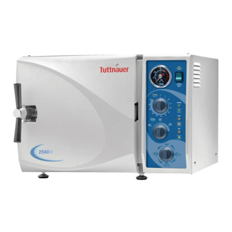
Page 9: Front View Model 2340/2540 M, Mk
FRONT VIEW MODEL 2340/2540 M, MK description description Water reservoir cover 10. Heat indicator light Water reservoir 11. Thermostat (B10) knob Safety valve 12. Multipurpose valve Air trap jet 13. Front legs Pressure gauge 14. Rear legs Main power switch 16. -
Page 10: Front View Model 3850/3870 M, Mk
FRONT VIEW MODEL 3850/3870 M, MK description description Water reservoir cover 10. Heat indicator light Water reservoir 11. Thermostat (B10) knob Safety valve 12. Multipurpose valve Air trap jet 13. Front legs Pressure gauge 14. Reservoir water drain valve Main power switch 15. -
Page 11: Rear View
REAR VIEW... -
Page 12: Maintaining And Replacing Parts
MAINTAINING AND REPLACING PARTS Safety Tests after Repair ATTENTION! After every repair or dismantling the enclosure, the autoclave should pass two safety electrical test by the Service Engineer. The following shall be performed: Warning! When re-installing the enclosure, connect the earthing to the cover. On installing the rear cover, connect the earthing before accomplishing the installation of the rear cover. -
Page 13: Dismantling The Outer Cover Of The Autoclave
Dismantling the Outer Cover of the Autoclave. Caution: Allow the instrument to cool before removing the outer covers. Warning: Before starting disconnect the instrument from the power source and make sure there is no pressure in the autoclave. Then proceed as follows: 1. -
Page 14: Cleaning And Replacing Air Trap Jet
Cleaning and Replacing Air Trap Jet (Located in the water reservoir) The elimination of air pockets from the sterilization chamber during heating and sterilization phases is achieved by means of the air trap jet. This device consists of a small orifice that is obtrusive and opened by a small wire moving forth and back. -
Page 15: Replacing The Safety Valve
Replacing the Safety Valve Caution Before starting, be sure that the electric cord is disconnected and that there is no pressure in the autoclave. Note: These instructions are valid for both, CE-marked and ASME type safety valves. 1. Remove the water reservoir cover. 2. -
Page 16: Replacing The Circuit Breaker
Replacing the circuit breaker Caution! Before starting, disconnect the instrument from the power source. 1. Remove the autoclave cover (see para. 6.2 “Dismantling the Outer Covers of the Autoclave”). 2. Disconnect the wires from the circuit breaker. 3. Remove the four screws connecting the circuit breaker to the panel (1). 4. -
Page 17: Temperature Safety Thermostat
Temperature Safety Thermostat (Located on the rear side of the heaters) The autoclave is supplied with a temperature thermostat that maintains the temperature during the dry stage, by connecting and disconnecting the electric power. This device automatically disconnects the heating elements in case of a rise in temperature. -
Page 18: Cut-Off Thermostat
Cut-Off Thermostat This thermostat cuts out power to the autoclave, in the event that all other safety systems do not function. For example: if the operator forgets to fill the chamber with water, and starts the sterilization cycle, the chamber will heat up and activate the cut-out thermostat. In order to restart the operation, press the RESET button. -
Page 19: Replacing Heating Elements
Replacing Heating Elements Caution: Before starting, ensure that the electric cord is disconnected from the power source and there is no pressure in the autoclave chamber. 1. Dismantle the autoclave cover (see para. 6.2 “Dismantling the Outer Covers of the Autoclave”). 2. -
Page 20: Replacing Multi-Purpose Valve
6.10 Replacing Multi-Purpose Valve Caution: Before starting, make sure that the electric cord is disconnected from the power source and there is no pressure in the autoclave chamber. 1. Dismantle the autoclave cover (see para. 6.2 “Dismantling the Outer Covers of the Autoclave”). 2. - Page 21 Position of Micro-Switches and their Operation Situation M.Sw Stage Fill Ste. Exh. + Dry M.Sw.1 Tight Tight Loose Loose M.Sw.2 Loose Loose Loose Tight M.Sw.3 Loose Loose Loose Tight Notes: Microswitches MSw1 - STER. and MSw. 2- DRY are actuated by the multi- purpose valve.
-
Page 22: Unclogging The Multi-Purpose Valve Or Chamber
6.11 Unclogging the multi-Purpose Valve or Chamber VERY IMPORTANT! When sterilizing cotton wool or pads, it is essential to wrap them in paper or cotton bags in order to prevent the multi-purpose valve and the autoclave openings from becoming clogged with remnants of the material. -
Page 23: Replacing The Door Bellows
6.13 Replacing the Door Bellows (Located in the Door Bridge) Caution: Before starting, be sure that there is no pressure in the autoclave chamber. 1. Open the door. 2. Unscrew and remove the tightening screw (5). 3. Gently pull out the door safety device locking pin (13). 4. -
Page 24: Replacing The Thermostat B10
6.14 Replacing the thermostat B10 Caution: Before starting, be sure that the electric cord is disconnected from the power source and that there is no pressure in the autoclave chamber. 1. Remove the autoclave cover (see para. 6.2 “Dismantling the Outer Covers of the Autoclave”). -
Page 25: Replacement Of The Door Cover
6.15 Replacement of the Door Cover Caution: Before starting, be sure that the electric cord is disconnected from the power source and that there is no pressure in the autoclave chamber. 1. Unscrew the four screws attaching the door cover and remove the door cover. - Page 26 Cat. No. Cat. No. No. Description Model No. Description Model 2340, 2540 BOL191-0032 washer All models ELE036-0009 screw 1730, 3140 spring All models SPR177-0012 BOL191-0091 3850, 3870 1730 POL065-0001 1730 BOL191-0140 2340, 2540 POL065-0053 door cover 2340, 2540 BOL191-0033 3140 COV314-0001 screw 3140...
-
Page 27: Replacing The Locking Device
6.16 Replacing the Locking Device Caution: Before starting, verify that there is no pressure in the autoclave chamber. 1. Remove the security ring (9) using a special tool. 2. Remove pin (6). 3. Remove locking device. Take care not to lose the Teflon disk (10). 4. -
Page 28: Replacing The Door Switch (Models 2540, 3150, 3850, 3870)
6.17 Replacing the Door Switch (models 2540, 3150, 3850, 3870) Caution! Before starting, disconnect the instrument from the power source and ensure that there is no pressure in the autoclave. Allow the autoclave to cool before removing outer covers. 1. Remove the autoclave cover (see para. 6.2 “Dismantling the Outer Covers of the Autoclave”). -
Page 29: Replacing The Drain Valve
6.18 Replacing the Drain Valve Caution! Before starting, disconnect the instrument from the power source and ensure that there is no pressure in the autoclave. Allow the autoclave to cool before removing outer covers. 1. Remove the autoclave cover (see para. 6.2 “Dismantling the Outer Covers of the Autoclave”). -
Page 34: General View Of Vessel, Door And Accessories
GENERAL VIEW OF VESSEL, DOOR AND ACCESSORIES Closing device Door Chamber... -
Page 35: Autoclave Cover
AUTOCLAVE COVER... -
Page 36: Door Tightening Bolt - Assembly
DOOR TIGHTENING BOLT – ASSEMBLY Cat. No. Description 1730, 2340, 2540 3140, 3850, 3870 Bushing LOK240-0003 LOK387-0003 Door tightening bolt assembly LOK240-0034 LOK387-0007 Locking screw housing LOK240-0005 LOK387-0006 Locking base LOK240-0030 LOK387-0012 Locking housing axis LOK240-0014 LOK387-0014 Door locking device pin LOK240-0019 LOK387-0016 Bakelite handle... -
Page 37: Multi-Purpose Valve Assembly
MULTI-PURPOSE VALVE ASSEMBLY Model 1730 Models 2340/2540/3140/3850/3870... -
Page 38: List Of Spare Parts
HEA009-0001 —— —— —— —— —— 350W 1730 M/E Heating Element, 120V, —— HEA009-0002 —— —— —— —— 350W 2340 M/E Heating Element, 120V, —— —— HEA009-0017 —— —— —— 350W 2540 M/E Heating Element, 230V, HEA009-0004 —— —— ——... - Page 39 Cat. No. Description 1730 2340 2540 3140 3850 3870 Heating Element, 240V, —— —— —— —— HEA009-0012 —— 800W, 3850 M/E Heating Element, 240V, —— —— —— —— —— HEA009-0013 600W, 3870 M/E Circuit Breaker, 1PH, ELE035-0069 ELE035-0069 ELE035-0069 ELE035-0069 —...
- Page 40 Cat. No. Description 1730 2340 2540 3140 3850 3870 Gasket, Door, Gray, — — — GAS080-0195 — — 31XX Gasket, Door, Green, — — — — GAS080-0198 GAS080-0198 38XX Disc, Silicone, Door GAS080-0006 GAS080-0006 GAS080-0006 GAS080-0006 GAS080-0006 GAS080-0006 Bellows Gasket, Silicone, Water GAS080-0007 GAS080-0007 GAS080-0007 GAS080-0007 GAS080-0007 GAS080-0007 Reservoir Cable, Plug+Socket...
- Page 41 Cat. No. Description 1730 2340 2540 3140 3850 3870 O-Ring (drain valve) GAS082-0021 GAS082-0021 GAS082-0021 GAS082-0021 GAS082-0021 GAS082-0021 6 x 2 Autoclave vessel ASM173-0001 ASM234-0001 ASM254-0001 CHM314-0000 ASM385-0001 ASM387-0001 Door Assembly DOR173-1000 DOR234-1000 DOR254-0000 DOR314-0000 DOR387-0001 DOR387-0001 Cooling coil PIP254-0041 PIP254-0041 PIP254-0041 PIP254-0041...
-
Page 42: Pressure Vs Temperature For Saturated Steam
PRESSURE VS TEMPERATURE FOR SATURATED STEAM psia InHg °F °C psia psig °F °C 2.95 114.5 0.10 45.8 17.1 219.7 1.18 117.9 104.3 4.44 129.3 0.15 54.1 17.2 219.9 1.18 118.6 104.4 5.90 140.2 0.20 60.1 17.2 220.1 1.19 118.6 104.5 7.39 149.1... - Page 43 psia psig °F °C psia psig °F °C 20.5 229.3 1.41 141.4 109.6 24.6 239.2 1.70 169.7 115.1 20.6 229.5 1.42 142.0 109.7 24.7 10.0 239.4 1.70 170.2 115.2 20.6 229.6 1.42 142.4 109.8 24.7 10.0 239.5 1.71 170.8 115.3 20.7 229.8 1.43...
- Page 44 psia psig °F °C psia psig °F °C 29.4 14.7 249.1 2.02 202.4 120.6 34.6 19.9 258.6 2.39 238.7 125.9 29.5 14.8 249.3 2.03 203.1 120.7 34.7 20.0 258.8 2.39 239.4 126.0 29.5 14.8 249.4 2.04 203.7 120.8 34.8 20.1 259.0 2.40 240.2...
- Page 45 psia psig °F °C psia psig °F °C 40.6 25.9 268.2 2.80 280.0 131.2 45.7 31.2 275.4 3.15 315.0 135.2 40.7 26.0 268.3 2.81 280.9 131.3 45.8 31.3 275.5 3.16 315.9 135.3 40.9 26.2 268.5 2.82 281.7 131.4 45.9 31.5 275.7 3.17 316.8...
-
Page 46: Drawing Of Electrical System Of Table Autoclave Models 1730M, Mk
DRAWING OF ELECTRICAL SYSTEM OF TABLE AUTOCLAVE MODELS 1730M, MK... -
Page 47: Drawing Of Electrical System Of Table Autoclave Models 2340/2540 M, Mk
DRAWING OF ELECTRICAL SYSTEM OF TABLE AUTOCLAVE MODELS 2340/2540 M, MK... -
Page 48: Drawing Of Electric System Of Table Autoclave Model 3140 M
DRAWING OF ELECTRIC SYSTEM OF TABLE AUTOCLAVE MODEL 3140 M... -
Page 49: Drawing Of Electric System Of Table Autoclave Models 3850 M
DRAWING OF ELECTRIC SYSTEM OF TABLE AUTOCLAVE MODELS 3850 M... -
Page 50: Drawing Of Electrical System Of Table Autoclave Models 3870 M
DRAWING OF ELECTRICAL SYSTEM OF TABLE AUTOCLAVE MODELS 3870 M... -
Page 51: Piping Diagram Table Top Autoclave Models: M And Mk
PIPING DIAGRAM TABLE TOP AUTOCLAVE MODELS: M AND MK...
Need help?
Do you have a question about the 2340 M and is the answer not in the manual?
Questions and answers