Table of Contents
Advertisement
Quick Links
Advertisement
Table of Contents

Subscribe to Our Youtube Channel
Related Manuals for Ultimaker PVA Removal Station


Summary of Contents for Ultimaker PVA Removal Station
- Page 1 Ultimaker PVA Removal Station Installation and user manual...
-
Page 2: Table Of Contents
5.2 Check the water saturation level 5.3 Disposal of wastewater 5.4 Storage 6. Troubleshooting 6.1 Failure modes 6.2 Error messages 7. Warranty 7.1 General 7.2 Conditions 7.3 Notification 7.4 Exclusions 7.5 Applicable law and competent court Ultimaker PVA Removal Station user manual... - Page 3 Disclaimer This manual sets out the instructions on how to install and operate the Ultimaker PVA Removal Station. Please read and understand the contents of this installation and user manual carefully. Failure to read the manual may lead to personal injury, inferior results, or damage to the Ultimaker product. Always make sure that anyone who uses this device knows and understands the contents of the manual.
-
Page 4: Safety And Compliance
1. Safety and compliance... -
Page 5: Safety Messages
Station while it is in operation. Always control the PVA Removal Station with the user interface at the front. • Do not change or adjust any parts of the PVA Removal Station unless the change or adjustment is authorized by the manufacturer. -
Page 6: Health And Safety
(1.5 EC Declaration of Conformity). The PVA Removal Station has a movable component in the form of a rotor. Although the force of the rotor is limited, do not touch the rotor during operation. When cleaning a printed product in the PVA Removal Station, make sure the product is placed inside the rinsing basket. -
Page 7: Ec Declaration Of Conformity
Stationsplein 32, 3511 ED Utrecht The Netherlands The Technical File is kept at the Manufacturer's address. Year of affixing CE marking: 2 2 0 0 2 2 1 1 Signed for and on behalf of Ultimaker BV: Utrecht, Miguel Calvo 01/Nov/21_______ The Netherlands CTO &... -
Page 8: Introduction
2. Introduction... -
Page 9: Main Components
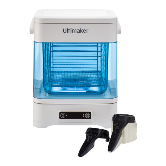
The simple but elegant interface has two buttons and and a large handle for easy transportation. The three small LEDs. Turn the PVA Removal Station on back of the container has a pouring spout to and off with the power button on the left. The button facilitate water disposal. -
Page 10: Specifications
0 – 32 °C (32 – 90 ºF) Relative humidity 10 - 90% RH non-condensing Electrical requirements Voltage 100 - 240 VAC Frequency 50 - 60 Hz Power Max. 600 W Warranty Warranty period 12 months Ultimaker PVA Removal Station user manual... -
Page 11: Installation
3. Installation... -
Page 12: Unboxing
8. Remove the top cover of the container and remove the protective material from the rinsing basket. 3.2 What’s in the box The Ultimaker PVA Removal Station consists of several components and accessories. Check if all items are included before continuing:... -
Page 13: Hardware Installation
3.3 Hardware installation After unboxing, complete the installation of the PVA Removal Station in only a few simple steps. Make sure that all packaging material is removed from the product and choose a suitable location to install the PVA Removal Station. -
Page 14: Operation
4. Operation... -
Page 15: Filling The Container
Note: Always first make sure the docking station is clean and dry. Remove all saturated PVA with a moist towel and dry the docking station before placing the container on top. Immediately unplug the PVA Removal Station if water has splashed over the docking station. Allow the docking station to air dry completely before next use. -
Page 16: Select Rotor Speed
4.3 Select rotor speed The PVA Removal Station is equipped with two rotor speed settings: Normal and Low. The Low speed mode is recommended for smaller, fragile printed objects. Additionally, a Pause mode is available to allow intermediate inspection of the part and dissolving process. -
Page 17: Remove The Print
PVA material has dissolved. Inspect the print 1. Turn off the PVA Removal Station by pressing the power button, or press the rotor button to activate the Pause mode (press twice when in Normal mode, press once when in Low mode). -
Page 18: Container Illumination
1. When the PVA Removal Station is turned off, press the power button and hold for 8 seconds. 2. The upper LED of the rotor speed indicator will light up. This indicated that the Brightness mode is enabled. -
Page 19: Maintenance
5. Maintenance... -
Page 20: Maintenance Schedule
5.1 Maintenance schedule To keep your PVA Removal Station in optimal condition, we recommend the following maintenance schedule, based on 2,000 operating hours per year: Ultimaker PVA Removal Station maintenance schedule Every month Refresh the water Check the water saturation level regularly and refresh (or every water exchange) the water according to the saturation indicator. -
Page 21: Check The Water Saturation Level
1. Remove the top cover and lift the rinsing basket out of the container. 2. Look down into the PVA Removal Station at the saturation indicator at the bottom. This is located on top of the magnetic rotor. -
Page 22: Storage
You can now refill the container for continued use or place it away in storage. 5.4 Storage The Ultimaker PVA Removal Station must be stored according to the specified ambient conditions (see section 2.2). Take the following actions to ensure the PVA Removal Station is stored safely and correctly: 1. -
Page 23: Troubleshooting
6. Troubleshooting... -
Page 24: Failure Modes
6.1 Failure modes If something goes wrong during operation of the PVA Removal Station, or the PVA Removal Station does not behave as expected, use the troubleshooting information provided to locate the root cause and solution for any issues. Failure mode... -
Page 25: Error Messages
6.2 Error messages If the PVA Removal Station encounters a technical issue, the rotor will stop and the interface will display an error message. The error can be caused by a hardware failure, negligence, or inappropriate use. Error messages will be presented in the form of both rotor speed LEDs blinking in a pattern. To determine the error code, count the number of times both LEDs flash, between a distinctive pause of 1 second. -
Page 26: Warranty
7. Warranty... -
Page 27: General
7.1 General Ultimaker grants a standard warranty on the Ultimaker S5 Pro Bundle (‘Product’) in the country where the product was purchased. From the date the product is sold and delivered to an end-customer for the first time, as evidenced by the original customer’s purchase invoice, Ultimaker warrants the product is free from defects in material, design and... -
Page 28: Notification
• Failure of the product caused by an accident. In any event, Ultimaker is not liable for indirect or consequential damages, including but not limited to loss of use, loss of profit or revenue. Furthermore, Ultimaker’s liability is limited to the purchase value of the product.
Need help?
Do you have a question about the PVA Removal Station and is the answer not in the manual?
Questions and answers