Sign In
Upload
Manuals
Brands
envea Manuals
Measuring Instruments
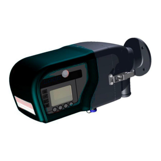
STACK 710
envea STACK 710 Measurement System Manuals
Manuals and User Guides for envea STACK 710 Measurement System. We have
1
envea STACK 710 Measurement System manual available for free PDF download: User Manual
envea STACK 710 User Manual (68 pages)
Particulate Measurement System
Brand:
envea
| Category:
Measuring Instruments
| Size: 2 MB
Table of Contents
Table of Contents
5
List of Figures
6
Introduction
9
Purpose of this Manual
9
Limits of Use
11
Additional Information
11
Certification
12
Product Description
13
Figure 1: STACK 710- General Overview
13
Installation Diagram
14
Figure 2: STACK 710- Installation Diagram
14
Installation Instructions
15
Installation Checklist
15
Selecting an Installation Location
15
Maintaining the Pathlength During Installation
16
Figure 3: STACK 710- Installation Schematic
16
Installing the Mounting Flanges
17
Figure 4: STACK 710- Pathlength Distance
17
Figure 5 Mounting Flange Schematic
17
Mounting Details
18
Flange Alignment Tool
18
Figure 6: Front View of Air Purge Showing Mounting Holes
18
Important Information for Installing the Transceiver and Retro-Reflector
19
Figure 7: Installing the Transceiver and Retro-Reflector (Side View)
19
Figure 8: Installing the Transceiver and Retro-Reflector (Top View)
19
Mounting the Transceiver and Retro-Reflector
20
Figure 9: Mounting the Transceiver and Retro-Reflector
20
Electrical Connections
21
3.10 Transceiver Connections
22
Figure 10: Transceiver Connections
22
3.11 Connection to ENVEA Control Unit
23
Figure 11: SPUR Unit Connections
23
3.12 Cable Specification
25
Figure 12: Electrical Connection Overview
25
PC Software (PC-ME DUST TOOLS)
26
Getting Started
27
User Interface
27
Figure 13: User Interface
27
Function Keys
28
STACK 710 Symbols
29
Glossary of Terms
30
Using the Instrument for the First Time
31
Align the Retro-Reflector
32
Figure 14: Opening the Retro-Reflector Case & Releasing the Reflector
32
Align the Transceiver
33
Figure 15: Aligning the Retro-Reflector
33
Setup Calibration Check Interval
34
Setup Current Loop Output
34
4.10 Setup Alarm
36
4.11 Calibration Check
36
4.12 Modbus Interface
36
4.13 Modbus Registers
38
Periodic Mode of Operation
40
Calibration Check
40
Figure 16: STACK 710- Transceiver
40
Calibration Audit
41
Clear Stack Calibration
42
Gravimetric Calibration (Isokinetic Calibration)
43
Setting Calibration Constants Manually
45
Theory of Operation and Application
48
General Outline
48
Beer-Lambert's Law
48
Figure 17: Beer-Lambert's Law
48
Pathlength Correction Factor (PLCF)
50
Figure 18: Double Pass System
50
Examples of Different Pathlength Correction Factors (PLCF)
52
Figure 19: Examples of Different Pathlength Correction Factors (PLCF)
52
Requirements for Environmental Legislation
53
Figure 20: STACK 710- Overview
53
Figure 21: STACK 710- Transceiver
54
System Specification
55
Maintenance
57
Identifying Faults
57
Fault Number List
58
Maintenance
59
Cleaning the Optical Surfaces
60
Transceiver Cover
60
Figure 22: STACK 710- Removing the Cover
60
Configuration Record Sheet
61
Envea Service and Support Centres
68
Advertisement
Advertisement
Related Products
envea STACK 602
envea SM-4
envea AirASafe 2 Ex
envea AirFlow P
envea CAIRNET
envea CAIRNET V2 2G/3G
envea CAIRNET V4
envea DensFlow
envea DensFlow HP
envea LAS 5000XD
envea Categories
Measuring Instruments
Industrial Equipment
Monitor
Laser Level
Accessories
More envea Manuals
Login
Sign In
OR
Sign in with Facebook
Sign in with Google
Upload manual
Upload from disk
Upload from URL