Table of Contents
Advertisement
Advertisement
Table of Contents

Related Manuals for Teltonika FMB204


Summary of Contents for Teltonika FMB204
- Page 1 FMB204 Quick Manual Advanced waterproof tracker v1.0...
-
Page 2: Table Of Contents
How to install USB drivers (Windows) ..........7 Configuration (Windows) ..............7 Quick SMS configuration ..............9 Mounting recommendations ............. 10 LED indications ................11 Characteristics................11 Basic characteristics ............... 11 Electrical characteristics ..............13 Safety information ..............14 Certification and Approvals ............15 FMB204 | Wiki... -
Page 3: Know Your Device
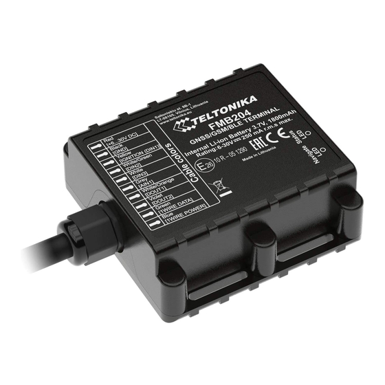
Know your device Figure 1 FMB204 device view FMB204 | Wiki... -
Page 4: Pinout
Pinout Table 1 FMB204 pinout Pin name Description VCC (6-30)V Power supply (6-30) V DC (+). GND (-) Ground pin. (6-30) V DC (-) DIN 1 Digital input, channel 1. DIN 2 Digital input, channel 2. DIN 3 Digital input, channel 3. -
Page 5: Wiring Scheme
Wiring scheme Figure 3 FMB204 Wiring scheme Automotive relay FMB204 | Wiki... -
Page 6: Set Up Your Device
5. After configuration, see “PC Connection (Windows)”, attach device cover back and screw in all screws. Figure 6 Micro-SIM card insert Figure 7 Battery connection 6. Device is ready to be mounted. Figure 9 Device is ready Figure 8 Attaching cover back FMB204 | Wiki... -
Page 7: Pc Connection (Windows)
Setup will continue installing the driver and eventually the confirmation window will appear. Click Finish to complete the setup. 1. Power-up FMB204 with DC voltage (6 – 30 V) power supply using power cable. LED’s should start blinking, see “LED Configuration (Windows) indications”. - Page 8 Most important configurator section is GPRS – where all your server and GPRS settings can be configured and Data Acquisition – where data acquiring parameters can be configured. More details about FMB204 configuration using Configurator can be found in our Wiki. Figure 12 Configurator Status window FMB204 | Wiki...
-
Page 9: Quick Sms Configuration
• • 2006 – Data sending protocol After successful SMS configuration, FMB204 device will (0 – TCP, 1 – UDP) synchronize time and update records to configured server. Time intervals and default I/O elements can be changed by using Teltonika Configurator parameters. -
Page 10: Mounting Recommendations
GND will be ▬ It is recommended to connect to the main power cable in unpredictable, which can lead to unstable FMB204 the fuse box. operation and even its failure. -
Page 11: Led Indications
Device is not working or Device is in boot mode Technology Quad-band 850 / 900 / 1800 / 1900 2G bands GPRS Multi-Slot Class 12 (up to 240 Data transfer kbps), GPRS Mobile Station Class B Data support SMS (text/data) FMB204 | Wiki... - Page 12 128MB internal flash memory LLS (Analog), ODBII dongle Fuel monitoring Physical specification Digital Input 1, Accelerometer, External Dimensions 72,5 x 73 x 27,3 mm (L x W x H) Power Voltage, Engine RPM (OBDII Ignition detection dongle) Weight 205 g FMB204 | Wiki...
-
Page 13: Electrical Characteristics
Output current (U > 3.0 V) Digital Input Short circuit current (U = 0) Input resistance (DIN1) 59.9 kΩ Input resistance (DIN2, DIN3) 67.5 kΩ Input voltage (Recommended Operating Conditions) Input Voltage threshold (DIN1) Input Voltage threshold (DIN2, DIN3) FMB204 | Wiki... -
Page 14: Safety Information
EN 60950-1 standard. Risk of explosion if battery is replaced by an incorrect The device FMB204 is not designed as a navigational device for boats. type. Dispose of used batteries according to the instructions. -
Page 15: Certification And Approvals
• FMB204 E-Mark • FMB204 RoHS • FMB204 Declaration of device operation temperature • This sign on the package means that it is necessary to read the User‘s Manual before your start using the device. Full User‘s Manual version can be found in our Wiki. -
Page 16: Warranty
More information can be found at teltonika.lt/warranty-repair • Repaired • Replaced with a new product • Replaced with an equivalent repaired product fulfilling the same functionality • TELTONIKA can also repair products that are out of warranty at an agreed cost. FMB204 | Wiki...
Need help?
Do you have a question about the FMB204 and is the answer not in the manual?
Questions and answers