Table of Contents
Advertisement
Quick Links
Advertisement
Table of Contents

Summary of Contents for Kalatec Automacao STR6-RS485
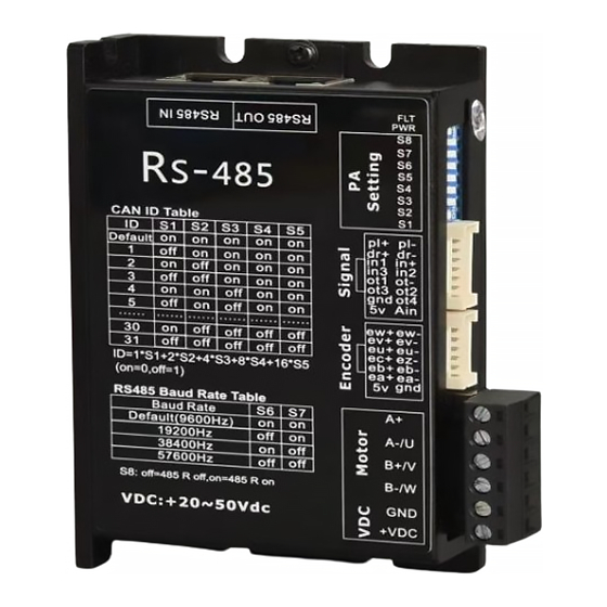
- Page 1 STR6-RS485 RS485 OPEN LOOP STEP MOTOR DRIVE User's Manual...
-
Page 2: Table Of Contents
Preface Foreword..................................3 1 Overview................................4 1.1 Product Introduction............................4 1.2 Characteristics..............................4 1.3 Application areas..............................5 2 Performance Index............................5 2.1 Electrical characteristics........................... 5 2.2 Use environment..............................6 3 Installation................................. 6 3.1 Mounting dimensions............................6 3.2 Installation method.............................7 3.3 4 Driver ports and wiring......................... 7 4.1 Schematic diagram of wiring..........................7 4.2 Port Definition..............................8 5 Instructions for setting the dial switch..................... -
Page 3: Foreword
Foreword Thank you for using our open step drive. Before using this product, please read this manual carefully to understand the necessary safety information, precautions, and operation methods.Incorrect operation can have extremely serious consequences. This product is designed and manufactured without the ability to protect personal safety from mechanical system threats. Users are advised to consider safety precautions during mechanical system design and manufacturing to prevent accidents caused by improper operation or product abnormalities. -
Page 4: Characteristics
1.2 Characteristics ●New 32-bit DSP technology ●1 way 0-5V analog input ●Four-way optocoupler isolated OC output ●Automatic parameter power-on setting function ●Variable current control greatly reduces the heat generation of the motor. ●The current is automatically halved at rest ●Can drive a variety of loop stepper motor ●5 photoelectricity isolation signal inputs, 2 of which are high-speed optocoupler isolation ●COMMUNICATION FREQUENCY UP TO 1MHZ (factory Default 9600HZ) -
Page 5: Use Environment
OC output pull-up voltage RS485 frequency 1000 Analog voltage input Insulation Resistance MΩ 2.2 Use environment Cooling Mode Natural Cooling or forced air cooling Cannotbeplacednexttootherheatingequipment,toavoiddust, oil mist, corrosive gases, humidity is too large and strong vibration sites, prohibited combustible gases and conductive Occasion dust。... -
Page 6: Installation
3 Installation 3.1 Mounting dimensions 3.2 Installation method Thereliableoperatingtemperatureofthedriverisusuallywithin60,andthe motor operating temperature is within 80℃。 It is recommended to use the automatic semi-flow mode when using the motor. When the motor stops, the current is automatically reduced by half to reduce the heat of the motor and the drive. -
Page 7: Driver Ports And Wiring
4 Driver ports and wiring 4.1 Schematic diagram of wiring 4.2 Port Definition 4.2.1LED Lamp status indication The blue LED on the left is the power indicator, which is always on when the driver is poweredon,and goes outwhen the driver cut soff the power. The blue LED is the fault indicator, When there is a fault,the indicator lamp for 3 seconds cycle flashing;... - Page 8 Over-tolerance alarm 4.2.2 Control Signal Input Port Control Signal interface Name Function HIGH-SPEED SIGNAL: Pulse rising edge is effective, PL highlevel 5 ~ 24 VDC, Low Level 0 ~ 0.5 v. In order to respond reliably to the pulse signal, the pulse width should be greater than 1.5 s.
- Page 9 Reserve Reserve Reserve 4.2.3 Encoder signal and Houle signal interface Name Function Closed-loop step-by-step encoder reservation Closed-loop step-by-step encoder reservation Closed-loop step-by-step encoder reservation Brushless reserve Brushless reserve Brushless reserve It supplies the motor's encoder and Houle element with a DC voltage of 5V and a current of 100mA.
- Page 10 DC Power Supply Positive Pole, supply voltage range: DC 24 ~ 75VDC, recommended +VDC 24VDC or 36VDC work. A phase winding interface for stepper motor,Open-loop steppingand closed-loop stepping are used, DC servo is not used for this interface A-phase winding interface of stepper motor B phase winding interface for stepper motor...
- Page 11 Pin Number Signal Function description RS485-SIGNAL, or B RS485- RS485 signal, or A RS485+ No, hold Signal ground EGNG Signal ground EGNG No, hold Signal hot ground shielding technology, used in EGNG strong interference Signal ground EGNG RS485-SIGNAL, or B RS485- RS485 signal, or A RS485+...
-
Page 12: Instructions For Setting The Dial Switch
Note: the above diagram is the definition diagram of network communication signal pin, the input/output is the same 5 Instructions for setting the dial switch RSO872 bus-type drive motor adopts 8-bit dial switch to set RS485 address, Baud rate and terminal matching resistance selection function, as follows: Note: Low 5-bit RS485 address is set by dialing, high 2-bit RS485 address is set by host computer. -
Page 13: Communication And Communication Protocol Description
Default (9600HZ, set by PC) 19200Hz 38400Hz 57600 Hz SW8:off=RS485 R off,(Default to)off; on= RS485 R on Note: The drive at the end of the network requires SW8 = on. 6 Communication and communication protocol description Network layout Built-in trapezoidal acceleration and deceleration curve generator, can trapezoidal acceleration and deceleration, through communication commands to achieve fixed-length operation, continuous operation, deceleration stop, immediately stop. -
Page 14: Communication Protocol
6.2 C ommunication protocol The communication adopts the standard Modbus protocol,which supports0x03(readregister), 0x06(writesingleregister),0x10(16)(writemultipleregisters).Serialcommunicationformat: baud rate 9600 ~ 115200,8 data bits, no parity check, 1 stop bit. 6.2.1 MODBUS Register address definition The parameter attri The range Register description site name bute defaul of values... - Page 15 rewrite when it is enabled. Current loop Ki R/W/S 0~32767 When self-setting s enabled, the item is read-only;The user can rewrite when it is enabled. Baud rate R/W/S 96~1152 96 said 9600 selection Effective R/W/S 3500 1~4200 Unit: Ma current value Device ID no.
- Page 16 Motor running R/W/S 0:Therunningdirection of the motor remains direction unchanged 1: the motor running direction is reversed Back to zero R/W/S 0~65535 pulse/s velocity Acceleration R/W/S 3200 0~65535 pulse/s^2 reduction is lower 16bit Deceleration R/W/S 0~65535 pulse/s^2 height 16bit 16bit R/W/S 1600 0~65535...
- Page 17 instruction Trigger the corresponding motion, and then the address changes to 6 0-- Slow down to a stop Forward constant length motion Reverse fixed length movement 3-- Forward continuous motion 4-- Continuous reverse motion 5-- Stop immediately Default value, meaningless Back to the 0-- Exit back to zero zero...
- Page 18 device control R/W/S See 2.2.1 for the register specific bit definition R/W/S 0~65535 1 said 50 us Return to zero limit filtering time device status See 2.2.2 for the register specific bit definition Save the Read the address: parameters Return 0: Save incomplete Return 1: The save is complete...
- Page 19 A definition Name & Description description default value 7~15 reserved IO triggers motion -- The trigger port enablement is inactive (In1 is the default -- The trigger port trigger port) can trigger the motion Reserved Negativelimitsignal Negative limit occurs level when (default IN3 is -- optocoupler is...
- Page 20 Movement to 1——内部脉冲发送 完成 0——内部脉冲 complete 未完成 1 -- Internal pulse transmission completed 0 -- Internal pulse is incomplete retain Negative limit 0——No negative limit signal 1-— a negative limit signal positive limit 0 -- No positive limit signal 1 -- Positive limit signal retain...
-
Page 21: Return To Zero Function
6.3 Return to zero function 6.3.1 The forward limit signal is zero to zero After writing "1" to register address 71 (return to zero command), the return to zero process is as follows: Step1:Runforwardtothepositivelimitatthespeedandaccelerationsetatregisteraddresses from 62 to 67. Step 2: Slow down and stop when positive limit signal is detected. Step 3: Run to the limit signal in the negative direction of the speed set at register address 60 (return to zero speed). -
Page 22: Modbus Common Function Code
6.4 MODBUS Common function codes 6.4.1 Read holding register command 0x03 Host -> Slave Data Device Function Register Number of address code address registers CRC check read Slave -> Host Data Device Function Number of Register CRC check address code bytes count returned... -
Page 23: Crc Validation Routines
6.4.3 Write multiple registers command 0x10 Host -> Slave Data Device Function Write Write Write address code starting number content content check address number bytes Slave -> Host Data Function The starting Write the CRC check code address number Write 14464 to the slave 16bit low (register address 64) and 16bit high (register address) 65) Write 1, that is, the total number of trips is 80000pulse. -
Page 24: Warranty And After-Sales Service
7 Warranty and after-sales service Please keep the packing box for transportation, storage or need to return to the company for maintenance.One year warranty period: From the use of this drive within one year because of the product itself caused by the damage, responsible for the warranty.
Need help?
Do you have a question about the STR6-RS485 and is the answer not in the manual?
Questions and answers