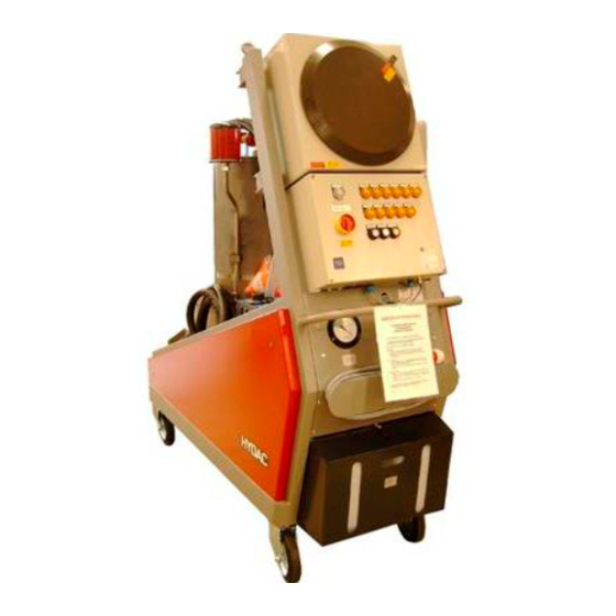
HYDAC FILTER SYSTEMS FluidAqua Mobil FAM 15 ATEX Operating And Maintenance Instructions Manual
Hide thumbs
Also See for FluidAqua Mobil FAM 15 ATEX:
- Operating and maitenance instructions (84 pages)

Subscribe to Our Youtube Channel
Related Manuals for HYDAC FILTER SYSTEMS FluidAqua Mobil FAM 15 ATEX


Summary of Contents for HYDAC FILTER SYSTEMS FluidAqua Mobil FAM 15 ATEX
- Page 1 FluidAqua Mobil FAM 15-70 /-EX02 II 2G IIB+H T4 (+10°C<Ta<40°C) Operating and Maintenance Instructions English (translation of original instructions) Documentation no.: 4510066...
-
Page 2: Imprint
++49 (0)6897 509 1394 E-mail: guenter.harge@hydac.com © HYDAC FILTER SYSTEMS GMBH All rights reserved. No part of this work may be reproduced in any form (print, photocopy or by other means) or processed, duplicated or distributed using electronic systems without the written consent of the publisher. -
Page 3: Table Of Contents
Content Content Imprint ........................2 Documentation Representative ................2 Content ........................3 Preface ........................5 Technical Support ....................6 Product modification ....................6 Warranty ....................... 6 Using the Documentation ..................7 General Safety Information ..................8 Hazard symbols ....................8 Signal words and their meaning in the general safety information ....... - Page 4 Content Operating elements on the unit ................39 Starting up the unit ....................41 Setting the vacuum pressure ................41 Venting the filter housing ..................42 Switching off FAM ....................43 FAM in manual operation ..................43 Error messages / troubleshooting ............... 44 [H5] If the vacuum column is overfilled, ...............
-
Page 5: Preface
If you discover errors while reading the documentation or have additional comments or suggestions, contact us at: HYDAC FILTER SYSTEMS GMBH Technische Dokumentation Postfach 12 51 66273 Sulzbach / Saar Germany We look forward to receiving your input. -
Page 6: Technical Support
Warranty For the warranty provided by us, please refer to the terms of delivery of HYDAC FILTER SYSTEMS GMBH. You will find these under www.hydac.com -> General terms and conditions. FAM 15-70 ATEX Page 6 / 88 BEWA FAM-15-70 II 2G IIB+H2 T4 EX02 4510066 en-us 2020-01-24.docx... -
Page 7: Using The Documentation
Preface Using the Documentation Note that the method described for locating specific information does not release you from your responsibility of carefully reading these instructions prior to starting the unit up for the first time and at regular intervals in the future. What do I want to know? I determine which topic I am looking for. -
Page 8: General Safety Information
General Safety Information General Safety Information The unit was built according to the statutory provisions valid at the time of delivery and satisfies current safety requirements. Any residual hazards are indicated by general safety information and instructions and are described in the operating instructions. Observe all safety and warning instructions attached to the unit. - Page 9 General Safety Information Risk of burns due to hot surfaces Substances that are health hazards or irritants Danger of explosion in explosive atmospheres This symbol marks safety indications that refer particularly to explosion protection. FAM 15-70 ATEX Page 9 / 88 BEWA FAM-15-70 II 2G IIB+H2 T4 EX02 4510066 en-us 2020-01-24.docx 2020-01-24...
-
Page 10: Signal Words And Their Meaning In The General Safety Information
General Safety Information Signal words and their meaning in the general safety information DANGER DANGER – The signal word indicates a hazardous situation with a high level of risk, which, if not avoided, will result lethal or serious injury. WARNING WARNING –... -
Page 11: Structure Of The General Safety Information And Instructions
General Safety Information Structure of the general safety information and instructions All warning instructions in this manual are highlighted with pictograms and signal words. The pictogram and the signal word indicate the severity of the danger. Warning instructions listed before an activity are laid out as follows: SIGNAL WORD Type and source of danger HAZARD SYMBOL... -
Page 12: Intended Use
General Safety Information Intended Use Use the unit only for the application described below. The FAM is for dewatering, filtering and degassing hydraulic and lubricating oils. In addition, it removes free water, emulsified water and a large percentage of the water found in solution. Proper or designated use of the product extends to the following: ... - Page 13 General Safety Information When work is done in explosion-prone areas, the safety of persons and equipment depends on the observance of all relevant safety regulations. The installation and maintenance personnel thus carries particular responsibility. Exact knowledge of the applicable regulations and conditions is required.
-
Page 14: Explosion Protection According To Eu Directive 2014/34/Eu
General Safety Information Explosion protection according to EU directive 2014/34/EU The dewatering unit FluidAqua Mobil of the FAM-ATEX series meets the requirements of the new EU Directive 2014/34EU for areas in which explosive gas atmospheres can occur. The designation of the explosion-proof ATEX-compliant FAM is: II 2G IIB+H T4 (+10°C<Ta<40°C) This means that the FAM may be used only in accordance with:... -
Page 15: Improper Use Or Use Deviating From Intended Use
Any use extending beyond this or deviating therefrom shall not be considered intended use. HYDAC Filter Systems GmbH will assume no liability for any damage resulting from such use. This risk is borne solely by the owner. Improper use may result in hazards and/or will damage the unit. Examples of improper use: ... -
Page 16: Qualifications Of Personnel / Target Group
General Safety Information Qualifications of personnel / target group Persons who work on the power unit must be aware of the associated hazards when using the power unit. Operating and specialist personnel must have read and understood the operating instructions, in particular the general safety information, and applicable regulations before beginning work. - Page 17 General Safety Information and water Proper and environmentally- Disposal Specialist personnel friendly disposal of materials and substances Decontamination of contaminants Knowledge about reuse FAM 15-70 ATEX Page 17 / 88 BEWA FAM-15-70 II 2G IIB+H2 T4 EX02 4510066 en-us 2020-01-24.docx 2020-01-24...
-
Page 18: Wear Suitable Clothing
General Safety Information Wear suitable clothing Loosely worn clothing increases the danger of getting caught or wound up in rotating parts and the danger of getting snagged on projecting parts. You can be severely injured or killed. Wear close-fitting clothing. ... -
Page 19: Transporting The Fam
Transporting the FAM Transporting the FAM CAUTION High empty weight (≈ 640 - 680 kg, depending on the version) Danger of bodily injury ► Use at least two persons to shift the mobile FAM. NOTICE Using components for pushing/pulling The FAM will be damaged ►... -
Page 20: Crane
Transporting the FAM Crane NOTICE Unsuitable lifting accessories The unit will be damaged / Components will be damaged / destroyed ► Use only suitable lifting accessories to raise or lash the FAM. ► Ensure that no forces from the lifting accessories are exerted on the components on the FAM. -
Page 21: Checking The Scope Of Delivery
Checking the scope of delivery Checking the scope of delivery Upon receiving the FAM check it for any damage in transit. The FAM may not be set up and installed unless it is in perfect order. Any damage in transit is to be reported to the forwarding agent or the department in charge immediately;... -
Page 22: Fam Description
FAM description FAM description The FluidAqua Mobil FAM ATEX was developed for the dewatering, filtration and degassing of hydraulic and lubricating oils. It removes free water, emulsified water and a large percentage of the water to be found in solution. The integrated fluid filter ensures an efficient separation of solid particles. -
Page 23: Fam Overview
FAM overview FAM overview FAM 15-70 ATEX Page 23 / 88 BEWA FAM-15-70 II 2G IIB+H2 T4 EX02 4510066 en-us 2020-01-24.docx 2020-01-24... - Page 24 FAM overview Item Description Suction screen Sight glass Inlet valve (2/2 directional control valve) Vacuum column Fluid level gauge Level switch Vacuum pressure gauge Ball valve for the manual drainage of the vacuum column Evacuation pump with electrical motor Pressure relief valve Fluid filter for separating solid particles Fluid filter differential pressure indicator Ball valve for the manual drainage of the fluid filter...
-
Page 25: Fam Components
FAM overview FAM components Item Description Suction screen Sight glass Inlet valve (2/2 directional control valve) Vacuum column Level switch Vacuum pressure gauge Evacuation pump with electrical motor Pressure relief valve Fluid filter for separating solid particles Float switch in the oil pan Vacuum pump Fill level switch (dry-running protection of the evacuation pump) Air filter and air dryer... -
Page 26: Description Of Function
Description of function Description of function Switch on the FAM at the main switch. After the "Start delay" switch is activated, the inlet valve opens and the vacuum pump builds up the necessary vacuum. This vacuum causes the fluid which is to be purified to be sucked into the vacuum column. -
Page 27: Hydraulicdiagram
Hydraulicdiagram Hydraulicdiagram FAM 15-70 ATEX Page 27 / 88 BEWA FAM-15-70 II 2G IIB+H2 T4 EX02 4510066 en-us 2020-01-24.docx 2020-01-24... - Page 28 Hydraulicdiagram Item Description Suction screen Sight glass Inlet valve (2/2 directional control valve) Vacuum column Fluid level gauge Level switch Vacuum pressure gauge Ball valve for the manual drainage of the vacuum column Evacuation pump with electrical motor Pressure relief valve Fluid filter for separating solid particles Fluid filter differential pressure indicator Ball valve for the manual drainage of the fluid filter...
-
Page 29: Using The Fam
Using the FAM Using the FAM Bypass purification The FAM is connected with suction and pressure lines to the tank and cleans the medium found there in continuous operation. Transfer by Pumping Contaminated oil Clean oil The FAM is connected to the contaminated oil tank by means of a suction line and pumps the fluid into the clean oil tank. -
Page 30: Connecting The Fam
Connecting the FAM Connecting the FAM All hoses on the FAM must be sufficiently conductive to properly discharge electrostatic charge buildup. If hoses are used, the ohmic resistance between the fittings—in this case between the FAM and the tank—may not exceed a limit value depending on the respective hose type. -
Page 31: Notes On Pipes And Hoses
Connecting the FAM Notes on pipes and hoses NOTICE Non-permitted pressure at the inlet IN / outlet OUT Risk of malfunctions ► Determine the pressure to be anticipated at the inlet/outlet with the prescribed values. Make sure that the cross-section of the connection lines is at least as large as the cross-section of the connection threads. - Page 32 Connecting the FAM In order to keep the pressure loss as low as possible, use as few threaded connections as possible. The pressure loss in a hydraulic line ( ) depends on the following: (line) Flow Kinematic viscosity ...
-
Page 33: Connecting The (In) Suction Port
Connecting the FAM Connecting the (IN) suction port NOTICE Overpressure at the suction port connection The unit will be damaged ► The maximum permitted pressure Pe perm at the inlet to the FAM can be found in the technical data. NOTICE Contamination too high The unit will be damaged... -
Page 34: Connecting The Pressure Connection / Return Flow Line (Out)
Connecting the FAM Connecting the pressure connection / return flow line (OUT) NOTICE Return port connection OUT closed off The unit will be damaged ► Check to be sure that all of the locking fixtures at the inlet/outlet are in "open"... -
Page 35: Electrical Connection Of The Fam
Connecting the FAM Electrical connection of the FAM DANGER Exposed electrical components in the switch cabinet Danger of fatal injury due to electric shock ► Any work involving the electrical system may only be done by a properly trained, certified electrician. -
Page 36: Rotating Field
Connecting the FAM Rotating field Make sure there is a clockwise rotating field. (the fan wheel turns to the left). If this is not the case, then the phases can be rotated in the 16A/32 A connection plug with the aid of the phase changing switch in the plug. The two phases at the mains plug must be exchanged in case of the 63A version. -
Page 37: Preparing The Rotary Vane Pump
Connecting the FAM Preparing the rotary vane pump As a basic rule, the rotary vane vacuum pump is not filled with oil at the time of delivery of the FAM. A sufficient amount of vacuum pump oil for the initial filling is included in the scope of delivery. -
Page 38: Filling The Seal Chamber Of The Evacuation Pump
Filling the seal chamber of the evacuation pump This vacuum pump oil is available from HYDAC under the following part no.: Description Packaging Part no.: Compressor oil - Leybold LVO 210 1 liters 3765250 Compressor oil - Leybold LVO 210 5 liters 3769255 Filling the seal chamber of the evacuation pump... -
Page 39: Operating Elements On The Unit
Operating elements on the unit Operating elements on the unit To operate the FAM, the following control and indicator elements are located on the operating panel: Function Quantity Numbering Function keys S1 - S3 Operating status lamps H1 - H4 Malfunction message lamps H5 - H14 H10 H11... - Page 40 Operating elements on the unit Operating status lamps: Inscription Operating state Start delay Startup phase Stop overrun After-run phase Malfunction Malfunction Fluid Aqua operates Purification operation FAM 15-70 ATEX Page 40 / 88 BEWA FAM-15-70 II 2G IIB+H2 T4 EX02 4510066 en-us 2020-01-24.docx 2020-01-24...
-
Page 41: Starting Up The Unit
Starting up the unit Starting up the unit NOTICE Connection IN / OUT closed FAM goes into error mode ► Check to be sure that all of the locking fixtures at the inlet/outlet are in "open" position each time during start-up. After you have made all connections and completed the preparations for commissioning, switch on the FAM at the main switch. -
Page 42: Venting The Filter Housing
Starting up the unit Venting the filter housing WARNING Hot fluid Risk of burns ► Make sure that hot fluid can exit when bleeding. NOTICE Air in the fluid filter The filter element is not utilized completely ► Bleed the fluid filter after each shut-down/filter element replacement The fluid filter is to be bled through the air-vent plug (X) in the cover until fluid emerges. -
Page 43: Switching Off Fam
Starting up the unit Switching off FAM Press key "Run-down [S2]". Now the unit starts with the after-running phase. The inlet valve closes, the vacuum pump is switched off, and the vacuum column is emptied. Wait until the lamp H2 goes out, then move the main switch to the "Off" position. -
Page 44: Error Messages / Troubleshooting
Error messages / troubleshooting Error messages / troubleshooting Signal Inscription Reason Rectification Vacuum Maximum filling level Reduce the vacuum in chamber [03] in the vacuum the vacuum column, overfilled column exceeded. e.g. from 300 mbar (absolute) to 400 mbar Possible foam (absolute), increase the formation in the heating temperature to... - Page 45 Error messages / troubleshooting Signal Inscription Reason Rectification filled. the FAM for leaks. Motor protection Electric motor of Switch on motor switch Q2/Q3 evacuation or vacuum protection in the pump overloaded. electronic control unit, check operating viscosity, drain fluid from vacuum pump, rinse and fill up with fresh water.
-
Page 46: [H5] If The Vacuum Column Is Overfilled
Error messages / troubleshooting [H5] If the vacuum column is overfilled, Description Malfunction: "Vacuum column overfilled" Press the RESET button. Select manual menu 1, and start the evacuation pump Can the vacuum column be emptied within 3.5°minutes from level 03 to level 01? ->... -
Page 47: [H6] Entry (In) Blocked
Error messages / troubleshooting [H6] Entry (IN) blocked Description Malfunction: "Inlet clogged" Cause: No medium is making it into the vacuum column Check the setting of the shut-off devices in the suction line. If they are closed, then open them. Check/clean the suction strainer. -
Page 48: [H7] Outlet (Out) Blocked
Error messages / troubleshooting [H7] Outlet (OUT) blocked Description Fault: "Outlet clogged" Cause: Medium cannot flow out of the vacuum column (evacuation pump pressure limit = 5 bar) Check the position of the shut-off devices in the return line. If they are closed, then open them. -
Page 49: [H8] V-Pump Temperature
Error messages / troubleshooting [H8] V-pump temperature Description Malfunction: "V-pump temperature" Cause: The vacuum pump temperature is too high Check the fill level in the vacuum pump. If necessary, fill up with the correct vacuum pump oil Press the RESET button to acknowledge/reset the fault. Does the malfunction recur after the vacuum pump has started? ->... -
Page 50: [H9] Wrong Phase Sequence
Error messages / troubleshooting [H9] Wrong phase sequence Description Malfunction: "Wrong motor rotation" Switch off and disconnect the power unit. Replace the phases on the mains plug and check the mains voltage. Switch on the power for the unit, and start it by pressing the main switch. -
Page 51: [H10] Change Fluid Filter
Error messages / troubleshooting [H10] Change fluid filter Description Malfunction: "Replace fluid filter" Press the RESET button to acknowledge/reset the fault. Switch off the unit at the main switch. Close the ball valves on the inlet IN and outlet OUT. Empty the filter housing via the drain ball valve. -
Page 52: [H11] Float Switch
Error messages / troubleshooting [H11] Float switch Description Malfunction: "Float switch" Empty the oil collecting pan. Press the RESET button to acknowledge/reset the fault. Start up the unit. Check the unit for leaks, and fix them. Does the error re-occur after ≈ 2 seconds? ->... -
Page 53: [H12] E/V/R Pump Motor Protection
Error messages / troubleshooting [H12] E/V/R pump motor protection Description Malfunction: "E/V/R pump motor protection" Switch off and disconnect the power unit. Open the control cabinet door. Switch the motor protection switch and/or fuse that was tripped back on and check the setting of the motor protection switch and/or the voltage capacity of the fuse in accordance with the motor type label and/or the heater type label. -
Page 54: [H13] Dry-Running, E-Pump
Error messages / troubleshooting [H13] Dry-running, E-pump Description Fault "Dry running, E-pump" Cause: Insufficient inflow into the vacuum column. The suction-side pressure loss is too great. Possible remedies: Clean the suction strainer. Lower the suction height. Reduce the absolute pressure in the vacuum column for example, from 500 mbar ->... -
Page 55: [H14] Level Switch 01/02(02/03)
Error messages / troubleshooting [H14] Level switch 01/02(02/03) Description Malfunction: Level switch 01/02(02/03) Switch off the unit at the main switch. Disconnect plug at the level sensor, and remove the level sensor. Manually check the switching points on the level switch ->... -
Page 56: [H15] V-Pump Pressure
Error messages / troubleshooting [H15] V-pump pressure Description Malfunction: "V-pump pressure" Cause: the pressure in the oil separator for the vacuum pump is too high. The air de-oiling element is used up / clogged. Replace the air de-oiling element. Press the RESET button to acknowledge/reset the fault. Does the malfunction recur after the vacuum pump has started? ->... -
Page 57: Performing Maintenance / Inspection
Performing maintenance / inspection Performing maintenance / inspection DANGER Risk of explosion Danger of fatal injury ► Perform all maintenance work outside of the ATEX danger zone. WARNING Hydraulic systems are under pressure Danger of bodily injury ► Relieve the pressure before performing any work. -
Page 58: Visual Checks
Performing maintenance / inspection Clean plastic parts only with a damp cloth. If defects which affect explosion protection are discovered during inspections, then the FAM is to be taken out of service until the defect is remedied. Repair and servicing work is not permitted on damaged flameproof enclosures (evacuation pump motor). -
Page 59: Overview Of Maintenance Intervals
Performing maintenance / inspection Overview of maintenance intervals Visual check for leaks Check threaded joints for fixed seat, tightening them as needed Check the measurement technology equipment / Underpressure manometer / Dynamic pressure manometer at the fluid filter Check fault indicator lamps Change the air filter (if this has not been required earlier) - Page 60 Performing maintenance / inspection Rotary Valve Pump Vacuum Pump Check oil level Check oil for discoloration. (See operating instructions of vacuum pump) Check that the oil filler neck and drain plug have been properly secured Check the vacuum pump for leaks.
- Page 61 Performing maintenance / inspection Fluid Filter Change the filter element (If this has not been required earlier) Oil mist separator Changing the filter element Electrics Carrying out an electrical test Measure the engine power consumption of all engines and compare the values with the type label t Perform electrical safety inspection in accordance with...
-
Page 62: Electrical Inspection
Performing maintenance / inspection Electrical inspection To open the switch cabinet, the cover stop screw is loosened and the pressure chamber cover opened counter-clockwise while using two removable handles (see picture). To close the cover, carefully screw it in up to the cover stop bolt, then tighten the bolt. - Page 63 Performing maintenance / inspection mechanical service life as specified by the manufacturer? Inspecting the SWITCH CABINET prior to commissioning Is the switch cabinet intact? Is the switch cabinet again installed in accordance with regulations? Is it certain that no foreign bodies or impermissible parts are located in the switch cabinet? Is the terminal chamber clean? Is the connection performed correctly?
-
Page 64: Filling The Seal Chamber Of The Evacuation Pump
Performing maintenance / inspection Filling the seal chamber of the evacuation pump Check the filling level of the reservoir to the seal chamber weekly; top off if necessary. For topping off, use the medium to be purified having a viscosity of ISO VG 10 …... -
Page 65: Lubricating Lock On The Electrical Cabinet
Performing maintenance / inspection Lubricating lock on the electrical cabinet NOTICE Corrosion on the lock of the electrical cabinet The lock cannot be opened / loss of ATEX approval ► Regularly inspect the lock for corrosion. ► Regularly lubricate the threads. To prevent corrosion on the lock (x) of the electrical cabinet, lubricate the threads on the closure regularly (x). -
Page 66: Replacing The Filter Element On The Fluid Filter
Performing maintenance / inspection Replacing the filter element on the fluid filter If the fault indicator lamp "Replace filter element" [H10]" lights up, replace the filter element on the fluid filter. See page 66 for details. To change the filter element, you need the following: ... - Page 67 Performing maintenance / inspection (1) Have a suitable tray on hand to catch the fluid. (2) Open the drain fitting, and collect the escaping fluid in the tray. Once the housing has been completely drained, close the drain fitting. Screw in the air bleed screw (x) by hand in a clockwise direction, and tighten it using a 10 mm Allen wrench.
- Page 68 Performing maintenance / inspection Turn the element locking cap on the top filter element by 90° in a counterclockwise direction (1) and remove the locking cap in an upwards direction (2). Turn all filter elements 90° in a counterclockwise direction, and remove them. FAM 15-70 ATEX Page 68 / 88 BEWA FAM-15-70 II 2G IIB+H2 T4 EX02 4510066 en-us 2020-01-24.docx...
- Page 69 Performing maintenance / inspection Dispose of the old filter elements in an environmentally friendly manner. Clean the inside of the filter housing of coarse dirt. Check the O-rings on the filter housing for damage. If necessary, replace them. Insert the filter element into the bayonet fitting (1) and lock it in place by turning each individual filter element by a 90°...
- Page 70 Performing maintenance / inspection Place the element locking cap on the upper filter element (1). Turn the locking cap 90° in the clockwise direction to lock it in place. No element locking cap = no filtration. Put the intermediate piece (b) on the lower section (c).
-
Page 71: Checking The Fault Indicator Lamp
Performing maintenance / inspection Fill the filter housing slowly. Slightly undo the air bleed screw (x). The air in the filter housing can escape via the slot on the air bleed screw. Bleed the filter housing with the air bleed screw (x) until operating fluid comes out. -
Page 72: Cleaning The Suction Strainer
Performing maintenance / inspection Cleaning the suction strainer NOTICE Missing suction strainer Pump is disrupted ► Replace suction strainer ► Clean the suction strainer regularly. To protect the pump from coarse contamination particles and other foreign bodies, a dirt trap with a strainer insert is fitted at the pump inlet. This strainer insert must be cleaned at regular intervals, e.g. -
Page 73: Changing The Air Filter Element
Performing maintenance / inspection Changing the air filter element You will require: Air filter (for part-no., see replacement parts list) Replace the air filter every six months. Replace it more frequently as required by the ambient air conditions (e.g., dusty/humid). ... -
Page 74: Vacuum Pump Maintenance
Performing maintenance / inspection Vacuum pump maintenance See also the enclosed operating instructions for the Leybold vacuum pump. Item Description Temperature measurement sensor Suction port connection Grounding connection Outlet Detonation flame arrester Oil filler neck Pressure switches Electrical connection Coupling FAM 15-70 ATEX Page 74 / 88 BEWA FAM-15-70 II 2G IIB+H2 T4 EX02 4510066 en-us 2020-01-24.docx... - Page 75 Performing maintenance / inspection Maintenance Description interval Before startup Check the level and the color of the oil (see Vacuum Pump Operating Instructions) Daily Check the level and the color of the oil (see Vacuum Pump Operating Instructions) Visually inspect the entire unit for leaks. Weekly Check the level and the color of the oil (see Vacuum Pump Operating Instructions)
-
Page 76: Filling The Vacuum Pump
Performing maintenance / inspection Filling the vacuum pump Max. Min. To fill the vacuum pump, open the fill plug [a]. Add oil until the level comes up to the MAX mark on the sight glass [b]. Check the oil level daily. When the fill level gets down to the MIN mark, add oil. -
Page 77: Checking The Vacuum Column Level Sensor
Performing maintenance / inspection Checking the vacuum column level sensor Conditions for check: 1. Pull out the power plug or deenergize the unit. Proceed as follows to dismantle the vacuum column level sensor: Remove the four nuts on the vacuum column cover. - Page 78 Performing maintenance / inspection Carry out the corresponding resistance measurement on the terminal +A2-X2:1 (5, 6, 7). In order to do this, remove the single leads from the terminals +A2- X2:5;6;7. Set the multimeter to resistance measurement. Insert the instrument leads on the multimeter into the bushings for resistance measurement.
-
Page 79: Testing The Float Switch In The Oil Pan
Performing maintenance / inspection Testing the float switch in the oil pan Proceed as follows to test the float switch in the oil pan: Use your fingers to raise the float switch in the oil pan. The unit must switch off and the fault message "Pan overfilled" must appear in display of the control panel. -
Page 80: Replacing Filter Element On The Oil Mist Separator
Performing maintenance / inspection Replacing filter element on the oil mist separator Item Description Separator head Separator pot Clogging indicator Filling level display The oil mist separator is located between the vacuum column and the vacuum pump. A filter element is used to retain the oil mist and the oil in the oil mist separator and the oil is collected in the separator pot, where it is continuously suctioned off and returned to the vacuum column. -
Page 81: Replacing The Filter Element On The Oil Mist Separator
Performing maintenance / inspection Replacing the filter element on the oil mist separator Quit automatic mode on the FAM. Afterwards, wait approximately ~1 minute, until normal pressure (ambient pressure) has been established in the vacuum column. Turn the separator pot (2) 1/8th of a turn to the left (bayonet seal) and remove it from the bottom. -
Page 82: Spare Parts And Accessories List
Spare parts and accessories list Spare parts and accessories list To ensure safe and reliable operation of the unit, use only original spare parts and accessories. When ordering spare parts, always indicate the unit designation with: type / material no. / serial no. / year of manufacture. Specify Description Part no. -
Page 83: Customer Support/Service
Customer Support/Service Customer Support/Service For product information or technical support or if you have comments or suggestions concerning this manual, please contact: HYDAC FILTER SYSTEMS GMBH Phone: ++49 (0) 6897 509 1174 Fax: ++49 (0) 6897 509 846 E-mail: filtersystems@hydac.com Regular inspection and maintenance work is indispensable for ensuring trouble-free operation and long service life for your FluidAqua Mobil. -
Page 84: Storing The Fam/Taking It Out Of Operation
Storing the FAM/Taking it out of Operation Storing the FAM/Taking it out of Operation Drain the FAM completely, including all of its components, before putting it into storage. Pull out the power plug, and securely fasten the hoses and power cord to the FAM. -
Page 85: Technical Data
Technical data Technical data FAM 15 FAM 30 FAM 50 FAM 70 ATEX ATEX ATEX ATEX Filter size OLF15 OLF 30 OLF 45 OLF 60 Filter element N15DMxxx N15DMxxx N15DMxxx N15DMxxx Content of filter housing 20 l 40 l 60 l 78 l Dirt holding capacity 500 g... -
Page 86: Model Code
Model Code Model Code Example: FAM - 50 - M - D - Z - 1 / -EX02-F Product FluidAqua Mobil Installation size ≈ 15 l/min ≈ 30 l/min ≈ 50 l/min ≈ 70 l/min Operating fluid Mineral oil – NBR seals, NBR houses, checked with mineral oil* Biologically quickly biodegradable (ester-based) –... - Page 88 HYDAC Filter Systems GmbH Industriegebiet Postfach 1251 66280 Sulzbach/Saar 66273 Sulzbach/Saar Germany Germany Tel: +49 (0) 6897 509 01 Central Fax: +49 (0) 6897 509 846 Technical Department Fax: +49 (0) 6897 509 577 Sales Internet: www.hydac.com E-Mail: filtersystems@hydac.com...
Need help?
Do you have a question about the FluidAqua Mobil FAM 15 ATEX and is the answer not in the manual?
Questions and answers