
Related Manuals for HYDAC FILTER SYSTEMS TCU Series


Summary of Contents for HYDAC FILTER SYSTEMS TCU Series
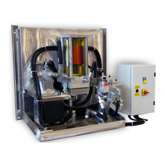
- Page 1 TransfomerCare Unit Operating and maintenance instructions English (translation of original instructions) Document no.: 3472805b...
-
Page 2: Trademarks
HYDAC FILTER SYSTEMS GMBH all rights reserved All rights reserved. This manual may not be reproduced in part or whole without the express written consent of HYDAC FILTER SYSTEMS GMBH. Contraventions are liable to compensation. Exclusion of Liability We made every endeavor to ensure the accuracy of the contents of this document. -
Page 3: Table Of Contents
Connecting the collecting canister float switch (optional)........29 Filling and bleeding the TCU and connections ........... 30 Bleeding the suction hose..................30 Filling and bleeding the TCU ................31 HYDAC FILTER SYSTEMS GMBH Page 3 / 64 BeWa TCU 3472805b en 2011-07-05.doc 2011-07-05... - Page 4 Setting the differential pressure relief valve ............58 Draining and decommissioning the TCU ............. 59 Disposing of the TCU ..................... 60 Spare parts and accessories................. 61 Technical Data ......................62 Customer Service....................62 HYDAC FILTER SYSTEMS GMBH Page 4 / 64 BeWa TCU 3472805b en 2011-07-05.doc 2011-07-05...
-
Page 5: Preface
If you discover errors while reading the documentation or have additional comments or suggestions, contact us at: HYDAC FILTER SYSTEMS GMBH Technische Dokumentation Postfach 12 51 66273 Sulzbach / Saar Germany The editorial department looks forward to receiving your input. -
Page 6: Technical Support
Warranty For the warranty provided by us, please refer to the General Terms of Sale and Delivery of HYDAC FILTER SYSTEMS GMBH. Refer to these at www.hydac.com General terms and conditions. HYDAC FILTER SYSTEMS GMBH Page 6 / 64 BeWa TCU 3472805b en 2011-07-05.doc... -
Page 7: Using The Documentation
The documentation number with its index enables you to order another copy of the operating and maintenance instructions. The index is incremented every time the manual is revised or changed. HYDAC FILTER SYSTEMS GMBH Page 7 / 64 BeWa TCU 3472805b en 2011-07-05.doc... -
Page 8: Safety Information And Instructions
Unit made by the user or purchaser Improper monitoring of unit components that are subject to wear and tear improperly performed repair work HYDAC FILTER SYSTEMS GMBH Page 8 / 64 BeWa TCU 3472805b en 2011-07-05.doc 2011-07-05... -
Page 9: Explanation Of Symbols And Warnings, Etc
Improper use may result in hazard to life and limb. Examples of improper use: Improper connection of the Unit voltage and sensor cables. Operation with non-approved fluids. HYDAC FILTER SYSTEMS GMBH Page 9 / 64 BeWa TCU 3472805b en 2011-07-05.doc 2011-07-05... -
Page 10: Informal Safety Precautions
Make the changes to the connections to the transformer only when the transformer has been shut down and grounded. Service work and sampling on the TCU can be performed with the transformer running. HYDAC FILTER SYSTEMS GMBH Page 10 / 64 BeWa TCU 3472805b en 2011-07-05.doc 2011-07-05... -
Page 11: Training And Instruction Of Personnel
Troubleshooting, electrical problem Maintenance Repair work Shutdown / decommissioning Transporting the TCU For transportation, lay the TCU with the rear side facing down onto a pallet. HYDAC FILTER SYSTEMS GMBH Page 11 / 64 BeWa TCU 3472805b en 2011-07-05.doc 2011-07-05... -
Page 12: Storing The Tcu
For identification details of the TransformerCare Unit, see the type label. This is located on the top of the unit and contains the exact product description and the serial number. HYDAC FILTER SYSTEMS GMBH Page 12 / 64 BeWa TCU 3472805b en 2011-07-05.doc... -
Page 13: Checking The Scope Of Delivery
Threaded connections, flanges etc. for connection to the transformer Items supplied NOTICE Impermissible operating media The unit will be damaged ► Operate the TCU with transformer oils only. HYDAC FILTER SYSTEMS GMBH Page 13 / 64 BeWa TCU 3472805b en 2011-07-05.doc 2011-07-05... -
Page 14: Tcu Features
Optimized : The TCU is equipped with a particle filter which also removes very small particles (from 3 μm). This not only increases the dielectric strength, but also increases the service life of the insulating oil. HYDAC FILTER SYSTEMS GMBH Page 14 / 64 BeWa TCU 3472805b en 2011-07-05.doc... -
Page 15: Tcu Components
It is protected against weathering by a cover made of ABS plastic. The electrical switching unit is to be mounted outside the cover depending on model. The components are as follows: HYDAC FILTER SYSTEMS GMBH Page 15 / 64 BeWa TCU 3472805b en 2011-07-05.doc 2011-07-05... - Page 16 (relative moisture) as a percentage. Gas withdrawal connection for taking gas samples. A small quantity of insulating oil required to lubricate and seal the internal vacuum pump is ejected here. HYDAC FILTER SYSTEMS GMBH Page 16 / 64 BeWa TCU 3472805b en 2011-07-05.doc 2011-07-05...
-
Page 17: Hydraulic Functions
(22). The volume flow at the inlet of the degasification and dewatering unit (8) is ~ 4.5 l/min. HYDAC FILTER SYSTEMS GMBH Page 17 / 64 BeWa TCU 3472805b en 2011-07-05.doc 2011-07-05... - Page 18 The TCU is not deactivated automatically when the stopping pressure (SP1) is reached. HYDAC FILTER SYSTEMS GMBH Page 18 / 64 BeWa TCU 3472805b en 2011-07-05.doc 2011-07-05...
- Page 19 Stopping pressure (SP1): 600 mbar. After expiry of a preset delay (K1), the TCU deactivates automatically. Atmospheric pressure 1013 The signal lamp illuminates Absolute pressure Absolute vacuum HYDAC FILTER SYSTEMS GMBH Page 19 / 64 BeWa TCU 3472805b en 2011-07-05.doc 2011-07-05...
-
Page 20: Electric Functions
The TCU is then restarted with a new delay time. If the system stops after restarting, this indicates a fault in the system. See chapter Measures to be taken if operation is stopped in this connection. HYDAC FILTER SYSTEMS GMBH Page 20 / 64 BeWa TCU 3472805b en 2011-07-05.doc... -
Page 21: Tcu Dimensions / Drilling Template
The TCU retaining frame has 4x Ø 10 mm mounting holes. The distance between the bore holes is 710 mm horizontally and 600 mm vertically. HYDAC FILTER SYSTEMS GMBH Page 21 / 64 BeWa TCU 3472805b en 2011-07-05.doc... -
Page 22: Installing The Tcu
The IP protection rating of the switch box is only guaranteed if the mounting method guarantees that the mounting holes are sealed. HYDAC FILTER SYSTEMS GMBH Page 22 / 64 BeWa TCU 3472805b en 2011-07-05.doc... -
Page 23: Notes On Piping / Hosing
= Pressure differential in [bar] = Flow rate [l/min] ~ 6 l/min = Kinematic viscosity [mm²/s] = Density [kg/dm³] = Line length [m] = Internal line diameter [mm] HYDAC FILTER SYSTEMS GMBH Page 23 / 64 BeWa TCU 3472805b en 2011-07-05.doc 2011-07-05... -
Page 24: Connecting The Suction Line
Connect the return hose (16), with the G3/8” adapter to the lower outlet (OUT) of the TCU. Do not connect the return hose to the transformer yet. HYDAC FILTER SYSTEMS GMBH Page 24 / 64 BeWa TCU 3472805b en 2011-07-05.doc... -
Page 25: Collecting The Lubricating And Sealing Oil
TCU. Collect the ejected quantity of oil in this canister. See Page 26 for a set of accessories "Collecting tank with float switch". HYDAC FILTER SYSTEMS GMBH Page 25 / 64 BeWa TCU 3472805b en 2011-07-05.doc... -
Page 26: Accessories "Collecting Canister With Float Switch
For monitoring the level in the collecting canister. It is electrically connected in series to the safety switch of the drip tray (see chapter ""). Strap to secure or fasten the collecting canister. HYDAC FILTER SYSTEMS GMBH Page 26 / 64 BeWa TCU 3472805b en 2011-07-05.doc 2011-07-05... -
Page 27: Electrical Connection Of The Tcu
An arrow on the housing shows the correct direction of rotation. If it is necessary to change the direction of rotation, change two phases in the connection housing of the electrical motor. HYDAC FILTER SYSTEMS GMBH Page 27 / 64 BeWa TCU 3472805b en 2011-07-05.doc... -
Page 28: Floating Contacts
Switches when the pressure reaches or exceeds the set alarm pressure of 24V DC at 0 VDC (pressure set alarm pressure). 9/13/14 Common GND for AquaSensor AS1000 and electronic pressure HYDAC FILTER SYSTEMS GMBH Page 28 / 64 BeWa TCU 3472805b en 2011-07-05.doc 2011-07-05... -
Page 29: Connecting The Collecting Canister Float Switch (Optional)
Connect the float switch of the collecting canister (see page 25) in series with the safety switch of the drip tray. Both switches are designed as normally open contacts. Terminal X2 Description 17+18 Connection of collecting canister float switch (optional) HYDAC FILTER SYSTEMS GMBH Page 29 / 64 BeWa TCU 3472805b en 2011-07-05.doc 2011-07-05... -
Page 30: Filling And Bleeding The Tcu And Connections
Connect the ball valve (5) with the suction hose (15) on the suction connection (INLET) of the TCU. It is located under the drip tray. Open the ball valve (5) fully and check the TCU for leaks. HYDAC FILTER SYSTEMS GMBH Page 30 / 64 BeWa TCU 3472805b en 2011-07-05.doc... -
Page 31: Filling And Bleeding The Tcu
Hold a container underneath it to catch the leaking oil! The connection fittings may be equipped with bleed screws. Close the connection. HYDAC FILTER SYSTEMS GMBH Page 31 / 64 BeWa TCU 3472805b en 2011-07-05.doc 2011-07-05... -
Page 32: Bleeding The Return Hose
Bleed the connection until no more air leaks out. Switch off the TCU and tighten the connection. Installation is now complete and the TCU is ready for start-up. HYDAC FILTER SYSTEMS GMBH Page 32 / 64 BeWa TCU 3472805b en 2011-07-05.doc... -
Page 33: Starting Up The Tcu
Check the TCU and the connections for leaks. If necessary, tighten leaking threaded connections. After start-up, check the Buchholz relay for air which may have entered and bleed it. HYDAC FILTER SYSTEMS GMBH Page 33 / 64 BeWa TCU 3472805b en 2011-07-05.doc 2011-07-05... -
Page 34: Tcu In Operation
Use a suitable screwdriver to turn the adjusting wheel on the time relay (K1) to the required time (~ 5 minutes). Close the cover of the electrical switch box and connect the electrical power supply again. HYDAC FILTER SYSTEMS GMBH Page 34 / 64 BeWa TCU 3472805b en 2011-07-05.doc 2011-07-05... -
Page 35: Setting The Electronic Pressure Switch (Eds)
It is then displayed for 3s. The maximum value can be reset in every display mode by briefly pressing ◄ and ► simultaneously. This process is acknowledged by the message "rES" on the display. HYDAC FILTER SYSTEMS GMBH Page 35 / 64 BeWa TCU 3472805b en 2011-07-05.doc... -
Page 36: Setting Eds Switchpoints For The Alarm And Stopping Pressure
= SP1 600 mbar. EDS factory settings Designation Value Alarm pressure = 500 Alarm pressure hysteresis = 10 Stop pressure = 600 Hysteresis stopping pressure = 10 HYDAC FILTER SYSTEMS GMBH Page 36 / 64 BeWa TCU 3472805b en 2011-07-05.doc 2011-07-05... -
Page 37: Setting Eds Hysteresis And Switchpoint
If a setting was changed, the display will briefly indicate "PROG" when returning to the previous display. The new setting has then been saved in the unit. HYDAC FILTER SYSTEMS GMBH Page 37 / 64 BeWa TCU 3472805b en 2011-07-05.doc... -
Page 38: Eds Error Messages
Possible causes include strong Contact HYDAC if the error still electromagnetic interference or a occurs. defective component. HYDAC FILTER SYSTEMS GMBH Page 38 / 64 BeWa TCU 3472805b en 2011-07-05.doc 2011-07-05... -
Page 39: Status Monitoring
] x 2 / 100 (abs) Example: Days 110 mbar x 2 / 100 = ~ 2.2% (abs) 50 mbar x 2 / 100 = ~ 1% (abs) HYDAC FILTER SYSTEMS GMBH Page 39 / 64 BeWa TCU 3472805b en 2011-07-05.doc 2011-07-05... -
Page 40: Continuous Water Content Monitoring (Optional)
-25 … 100°C. This is output like the saturation as a 4 … 20mA signal. The 4 … 20mA signals are fitted in the switch box (see Page 28). HYDAC FILTER SYSTEMS GMBH Page 40 / 64 BeWa TCU 3472805b en 2011-07-05.doc... -
Page 41: Checking The Gas And Water Content In The Oil
Unscrew the adapter until the check valve of the measurement coupling closes. Position the clamps as close as possible to the glass flask and tighten them. Screw the dust cap onto the measurement point. HYDAC FILTER SYSTEMS GMBH Page 41 / 64 BeWa TCU 3472805b en 2011-07-05.doc 2011-07-05... - Page 42 Please note that cooling the volume of the oil is reduced when it cools, which releases dissolved gases and a gas bubble may become visible. This is a normal reaction. HYDAC FILTER SYSTEMS GMBH Page 42 / 64 BeWa TCU 3472805b en 2011-07-05.doc...
-
Page 43: Specifying The Gas Formation Rate Of The Transformer
(solid insulation) into the oil, before they can be removed. HYDAC FILTER SYSTEMS GMBH Page 43 / 64 BeWa TCU 3472805b en 2011-07-05.doc... - Page 44 8 … 20 liters / 24 hours for transformers with open expansion vessels. The total quantity of withdrawn gases (ml / day) depends directly on the quantity of gases which reach the transformer via the expansion vessel. HYDAC FILTER SYSTEMS GMBH Page 44 / 64 BeWa TCU 3472805b en 2011-07-05.doc...
- Page 45 Atmospheric pressure (where available) Saturation (relative moisture) and temperature of the oil (when AquaSensor AS 1000 available) Upper and lower pressure of the degasification and dewatering unit HYDAC FILTER SYSTEMS GMBH Page 45 / 64 BeWa TCU 3472805b en 2011-07-05.doc 2011-07-05...
- Page 46 … 1060 10000 According to EN60599 / IEC 10/629, the upper values can be assumed as guideline values if the transformer manufacturer has not provided data. HYDAC FILTER SYSTEMS GMBH Page 46 / 64 BeWa TCU 3472805b en 2011-07-05.doc 2011-07-05...
-
Page 47: Checking The Tcu / Servicing
Checking the TCU / Servicing Regular system checks and service consists of the following actions: Periodical check-up - monthly Maintenance - annual General overhaul HYDAC FILTER SYSTEMS GMBH Page 47 / 64 BeWa TCU 3472805b en 2011-07-05.doc 2011-07-05... -
Page 48: Periodical Check-Up - Monthly
Saturation (relative moisture) of the oil (where available) b. Upper and lower pressure of the degasification and dewatering unit Cycle time of the degasification and dewatering unit (average of 5 cycles) HYDAC FILTER SYSTEMS GMBH Page 48 / 64 BeWa TCU 3472805b en 2011-07-05.doc... -
Page 49: Checking The Degasification And Dewatering Unit For Function
50. Clean the valve every year. The unit must be checked in the manufacturer's plant or by a service technician if no air movement is visible within ~ 5 minutes. HYDAC FILTER SYSTEMS GMBH Page 49 / 64 BeWa TCU 3472805b en 2011-07-05.doc 2011-07-05... -
Page 50: Cleaning The Check Valve Of The Degasification And Dewatering Unit
Insert one (A) M3 x 50 mm screw (included) into the valve element. Release the spring retainer. Push the spring retainer to one side. Remove the spring. HYDAC FILTER SYSTEMS GMBH Page 50 / 64 BeWa TCU 3472805b en 2011-07-05.doc 2011-07-05... - Page 51 Clean the valve seating in the lower section with a lint-free cloth. Check that the O-ring at the valve holder is securely held in place. Reverse the process to install the valve. HYDAC FILTER SYSTEMS GMBH Page 51 / 64 BeWa TCU 3472805b en 2011-07-05.doc 2011-07-05...
-
Page 52: Changing The Filter Element
Open the bleed plug in the cover of the filter housing. The oil is sucked from the filter housing into the degasification unit. Unscrew the 4 screws on the filter housing cover counter-clockwise. HYDAC FILTER SYSTEMS GMBH Page 52 / 64 BeWa TCU 3472805b en 2011-07-05.doc 2011-07-05... - Page 53 Activate the automatic shut-off valve (9) until oil escapes via the bleed screw. The system has now been bled. Tighten the bleed screw. The filter element change is now complete. HYDAC FILTER SYSTEMS GMBH Page 53 / 64 BeWa TCU 3472805b en 2011-07-05.doc 2011-07-05...
-
Page 54: Checking The Safety Switch Of The Drip Tray For Function
In the general overhaul, all wearing parts and seals are replaced. Further measures are performed after having checked the state of the unit. HYDAC FILTER SYSTEMS GMBH Page 54 / 64 BeWa TCU 3472805b en 2011-07-05.doc... -
Page 55: Troubleshooting And Measures After An Alarm/Failure
DGA (analysis of the gas in the oil). Inform the person responsible for operating this unit of this malfunction. Note the new point set in the record book. Resume operation. HYDAC FILTER SYSTEMS GMBH Page 55 / 64 BeWa TCU 3472805b en 2011-07-05.doc 2011-07-05... -
Page 56: Measures To Be Taken If Operation Is Stopped
If the electric motor does not start, or if it starts but the motor circuit breaker triggers, the electric motor or the motor pump group must be replaced. HYDAC FILTER SYSTEMS GMBH Page 56 / 64 BeWa TCU 3472805b en 2011-07-05.doc... -
Page 57: Checking The Pump Pressure / Pressure Restriction Valve
If the pressure gauge shows <>18 bar, you must set the differential pressure relief valve, see page 58. HYDAC FILTER SYSTEMS GMBH Page 57 / 64 BeWa TCU 3472805b en 2011-07-05.doc 2011-07-05... -
Page 58: Setting The Differential Pressure Relief Valve
Set the required pressure of 18 bar on the setscrew (A) using a screwdriver. Tighten the counternut (B), holding the setscrew (A) in the correct position. Replace the black lid onto the differential pressure relief valve. HYDAC FILTER SYSTEMS GMBH Page 58 / 64 BeWa TCU 3472805b en 2011-07-05.doc... -
Page 59: Draining And Decommissioning The Tcu
Open the bleed nozzle in the head of the degasification and dewatering unit. The oil now flows out of the degasification and dewatering unit. Unscrew the 4 screws on the filter housing cover counter-clockwise. HYDAC FILTER SYSTEMS GMBH Page 59 / 64 BeWa TCU 3472805b en 2011-07-05.doc 2011-07-05... -
Page 60: Disposing Of The Tcu
This applies in particular to the oil contained in the unit, to components coated in oil and to electronic components. After disassembling the unit and separating the various materials, reuse them or dispose of them properly in accordance with local regulations. HYDAC FILTER SYSTEMS GMBH Page 60 / 64 BeWa TCU 3472805b en 2011-07-05.doc 2011-07-05... -
Page 61: Spare Parts And Accessories
Gas sampling bag for TCU to determine the gas formation 3568340 rate (see Page 43). Adapter hose to attach the gas sampling bag (see Page 3572270 43). HYDAC FILTER SYSTEMS GMBH Page 61 / 64 BeWa TCU 3472805b en 2011-07-05.doc 2011-07-05... -
Page 62: Technical Data
HYDAC Service GmbH Rehgrabenstrasse 3 66125 Saarbrücken - Dudweiler Germany Telephone: ++49 (0) 6897 509 – 883 Fax: ++49 (0) 6897 509 – 324 E-mail: service@hydac.com HYDAC FILTER SYSTEMS GMBH Page 62 / 64 BeWa TCU 3472805b en 2011-07-05.doc 2011-07-05... - Page 63 Notes...
- Page 64 HYDAC FILTER SYSTEMS GMBH Industriegebiet Postfach 1251 66280 Sulzbach / Saar 66273 Sulzbach / Saar Germany Germany Phone: +49 (0) 6897 509 01 Central Fax: +49 (0) 6897 509 846 (Technical Department) Fax: +49 (0) 6897 509 577 (Sales Department) Internet: www.hydac.com...
Need help?
Do you have a question about the TCU Series and is the answer not in the manual?
Questions and answers