
Subscribe to Our Youtube Channel
Related Manuals for iLiving ILG8HVLS72


Summary of Contents for iLiving ILG8HVLS72
- Page 1 Industrial BLDC Ceiling Fan Owner’s Manual Model No.: ILG8HVLS72/ILG8HVLS88/ ILG8HVLS96/ILG8HVLS108 IMPORTANT INSTRUCTIONS READ & SAVE THESE INSTRUCTIONS...
-
Page 2: Table Of Contents
TABLE OF CONTENTS General Safety Instructions………………………………..…..……. Specifications ………………………........... Parts of the ceiling fan ....……………………….……..…..… Installation Instructions …………………….....….……..…..… 8-14 Remote Control & Operating Instructions …………………..……..… 15-17 Maintenance and Cleaning ……………………………....…. Troubleshooting …………………………………………....…. Warranty Information ……………………………………...………. -
Page 3: General Safety Instructions
GENERAL SAFETY INSTRUCTIONS Read instructions carefully before assembling or installing your fan. It is important that you observe all safety information to help prevent personal injury and/or property damage. 1. Installation work and electrical wiring should be done by qualified person only in accordance with all applicable codes and standards. -
Page 4: Specifications
If you think batteries might have been swallowed or placed inside any part of the body, seek immediate medical attention. Suitable for Commercial or Industrial Use Only. Specification Model# ILG8HVLS72 ILG8HVLS88 ILG8HVLS96 ILG8HVLS108 Size(inch) 72"... -
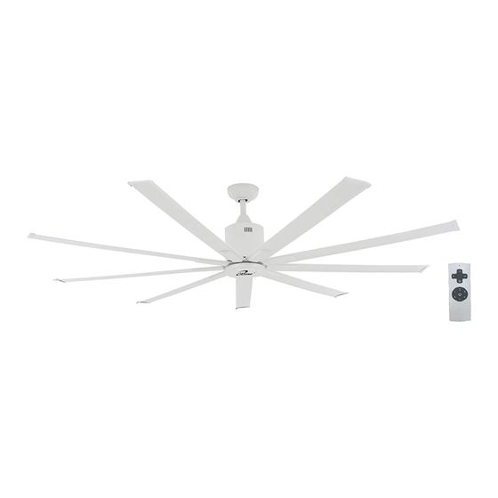
Page 5: Parts Of The Ceiling Fan
PARTS OF THE CEILING FAN DESCRIPTION SP-HVLS-1 Mounting Bracket SP-HVLS-2 Downrod/Ball Joint Assembly SP-HVLS-3 Canopy SP-HVLS-4 Canopy Cover SP-HVLS-1 SP-HVLS-5 Downrod Cover SP-HVLSxxx-6 Motor Assembly SP-HVLS-7 Fan Blade Holder SP-HVLS-2 SP-HVLSxxx-8 Fan Blade SP-HVLS-9 Fan Blade Cap SP-HVLS-10 Fan Blade Screw Cover SP-HVLS-11 Bottom Cover SP-HVLS-3... - Page 6 DESCRIPTION 10# 32x3/4 SCREW WIRE CAPS 3/16 * 2 INCH WOOD SCREW +Ф5.5xФ25xT1.5 LOCK WASHER (For cUL only) MOUNTING PIN M5x10mm LONG SCREW COTTER PIN 1/4-20x5/16”LONG SCREW Ф6 LOCK WASHER M4x6mm LONG SCREW Ф4 PLAIN WASHER Ф5 LOCK WASHER M5x8mm LONG SCREW REMOTE AND REMOTE BRACKET BATTERY...
- Page 7 Dimensions (inch) Model# ILG8HVLS72 16-3/4 ILG8HVLS88 16-3/4 ILG8HVLS96 16-3/4 ILG8HVLS108...
-
Page 8: Installation Instructions
INSTALLATION INSTRUCTIONS WARNING To avoid possible electrical shock, be sure electricity is turned off at the main fuse box before hanging. (Figure 1) NOTE: If you are not sure if the outlet box is grounded, contact a licensed electrician for advice, as it must be grounded for safe operation. - Page 9 Before installation, check that the outlet box is securely installed in place and it is able to support at least the fan weight. Securely attach the mount bracket to ceiling outlet box acceptable for ceiling fan support. Leveled Ceiling Angled Ceiling Mounting Mounting Attention...
- Page 10 Install the fan assembly to the mount bracket as shown below: Route wires and safety cable through downrod cover, canopy cover and ceiling canopy. Install the downrod with motor assembly through the canopy, canopy cover and downrod cover. Remove the two set screws from the downrod and retain for reinstallation.
- Page 11 Install the fan assembly to the mount bracket as shown below. Rotate till notch on the ball joint catches the stopper on the mounting bracket.
- Page 12 Attach th Connect wires to supply/grounding wires using connectors as shown below. e safety cable with (H3) 3/16 * 1-1/2 inch wood screw +Ф5.5xФ25xT1.5 lock washer to the ceiling . Conductor of a fan identified as grounded conductor to be connected to a grounded conductor of power supply, conductor of fan identified for equipment grounding to be connected to an equipment-grounding conductor.
- Page 13 Remove the two screws from the mount bracket. Assemble the canopy by tighten the screws. Securely attach and tighten the canopy cover. Rotate canopy until lock pin of mounting bracket is engaged with canopy, then tighten the screws till the keyhole is locked.
- Page 14 Assemble the fan blade to the fan M5x10mm blade holder with (H5) long screw and (H11) Ф5 lock washer. Repeat this step for all 9 fan blades. Rotate the bottom cover to the fan assembly until tighten.
-
Page 15: Remote Control & Operating Instructions
REMOTE CONTROL & OPERATION Button Description Power ON/Off Speed 1 (Minimum) Speed 2 Speed 3 Speed 4 Speed 5 Speed 6 (Maximum) Direction Control (Clockwise/Counterclockwise) 2H 4H 8H Timer Setting HOW TO INSERT BATTERY NOTE: Remove the batteries if the remote control is not to be used for a month or more. Batteries left in the unit may leak and cause damage. - Page 16 REMOTE CONTROL OPERATION INSTRUCTIONS (1) After the ceiling fan has been installed according to the assembly procedure and connected according to power supply specifications, perform the remote control and ceiling fan pairing procedure (refer to the remote control pairing method below).
- Page 17 5. Direction control Press the Direction Control can change the fan blade rotate direction. When the fan blade rotates clockwise (Summer Mode) and the air will blow down. A downward air flow creates a cooling effect.This allows you to set your air conditioner on a higher temperature setting without affecting your comfort.
-
Page 18: Maintenance And Cleaning
MAINTAINANCE 1. Because of the fan’s natural movement, some connections and screws may become loose. Check the support connections, brackets, and blade attachments at least twice a year to make sure they are secure. 2. Clean the fan periodically to help maintain the appearance. Do not use water when cleaning. This could damage the motor, or possibly cause electric shock. -
Page 19: Warranty Information
Love it? Help us make the product more for you. Let us know with a customer review. Please visit: https://www.amazon.com/review/review-your-purchases# At iLiving USA, we are committed to bringing top quality products to our customers. iLIVING USA 860 Mahler Road, Burlingame, CA 94010...
Need help?
Do you have a question about the ILG8HVLS72 and is the answer not in the manual?
Questions and answers