
Related Manuals for iLiving ILG8SF10V-T


Summary of Contents for iLiving ILG8SF10V-T
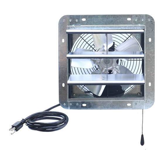
- Page 1 MULTI-SPEED SHUTTER MOUNTED EXHAUST FAN WITH THERMOSTAT Models: ILG8SF10V-T/ILG8SF12V-T/ILG8SF14V-T/ ILG8SF16V-T/ILG8SF18V-T/ILG8SF20V-T/ ILG8SF24V-T/ILG8SF30V-T OWNER'S MANUAL PLEASE READ AND SAVE THESE INSTRUCTIONS...
-
Page 2: Before You Begin
PLEASE READ AND SAVE THESE INSTRUCTIONS. READ CAREFULLY BEFORE ATTEMPTING TO ASSEMBLE, INSTALL, OPERATE, OR MAINTAIN THE PRODUCT DESCRIBED. PROTECT YOURSELF AND OTHERS BY OBSERVING ALL SAFETY INFORMATION. FAILURE TO COMPLY WITH INSTRUCTIONS COULD RESULT IN PERSONAL INJURY AND/OR PROPERTY DAMAGE! RETAIN INSTRUCTIONS FOR FUTURE REFERENCE. -
Page 3: Important Safety Instructions
IMPORTANT SAFETY INSTRUCTIONS Fans are UL/CUL Listed, Standard 507. 1. Do not depend on any switch as the sole means of disconnecting power when installing or servicing the fan. 2. Always disconnect, lock-out, and tag-out power source before installing or servicing. Failure to disconnect power source can result in fire, shock, or serious injury. -
Page 4: Installation Instructions
INSTALLATION INSTRUCTIONS INSTALLATION INSTRUCTION WARNING – TO REDUCE THE RISK OF FIRE, ELECTRIC SHOCK, OR INJURY TO PERSONS, OBSERVE THE FOLLOWING: a) Use this unit only in the manner intended by the manufacturer. If you have questions, contact the manufacturer. b) Before servicing or cleaning unit, switch power off at service panel and lock the service disconnecting means to prevent power from being switched on accidentally. - Page 5 Minimum Fan Model Screw Size Screw Picture Thickness Wooden 10mm All Models 3/16“ x 1-1/4“ Plank 3. Please ensure the space has a gap for enough air to get into the space. The fan installed on free space of at least 100mm above the upper edges of the corner.
-
Page 6: Wiring Diagram
Wiring Diagram Thermostat Temperature Range: 32˚F~130˚F (0˚C~54˚C) For ILG8SF10V-T/ILG8SF12V-T/ ILG8SF14V-T For ILG8SF16V-T... - Page 7 For ILG8SF18V-T For ILG8SF20V-T/ ILG8SF24V-T For ILG8SF30V-T...
-
Page 8: Dimensions (Inches)
Power source 115V, 60Hz Mounting Position Vertical Frame Material Galvanized Steel Shutter Blade Material Aluminum Alloy Propeller Material Aluminum Alloy and Galvanized Steel Agency Compliance UL/CUL 507 Dimensions (Inches) For ILG8SF10V-T/ ILG8SF12V-T/ ILG8SF14V-T... - Page 9 For ILG8SF16V-T/ ILG8SF18V-T/ ILG8SF20V-T/ ILG8SF24V-T/ ILG8SF30V-T Prop. Suggested wall MODEL Dia. opening (Sq) ILG8SF10V-T 10" 13" 13" 4 17/32" 2" 5 7/8" 11 21/32" 10 1/8" 10 1/8" 6" 3 17/32" 9/32" 1/2" 10 1/2" ILG8SF12V-T 12" 15" 15" 5 3/4"...
- Page 10 This is your ideal setting. The fan will start automatically when the room temperature raise above this set point, and will turn off when the set point is reached. A. Thermostat Switch B. Thermostat Knob C. Pull Chain Thermostat control panel For ILG8SF10V-T/ ILG8SF12V-T/ For ILG8SF16V-T/ ILG8SF18V-T/ ILG8SF14V-T ILG8SF20V-T/ ILG8SF24V-T/ ILG8SF30V-T...
-
Page 11: Troubleshooting
MAINTAINANCE 1. Disconnect power source before servicing. 2. Periodically clean off accumulated dirt from the propeller, guard, motor, and shutter. Do not depend on any switch as the sole means of disconnecting power when installing or servicing. If power disconnect is not visible, utilize OSHA Lock out/Tag out procedure. - Page 12 Love it? Help us make the product more for you. Let us know with a customer review. Please visit: https://www.amazon.com/review/review-your-purchases# At iLiving USA, we are committed to bringing top quality products to our customers. iLIVING USA 860 Mahler Road, Burlingame, CA 94010...
Need help?
Do you have a question about the ILG8SF10V-T and is the answer not in the manual?
Questions and answers