Emerson Micro Motion 1600 Installation Manual
Hide thumbs
Also See for Micro Motion 1600:
- Configuration and use manual (234 pages) ,
- Installation manual (52 pages)

Related Manuals for Emerson Micro Motion 1600


Summary of Contents for Emerson Micro Motion 1600
- Page 1 Installation Manual 00825-0100-1600, Rev AB March 2022 ™ Micro Motion 1600 Ethernet Transmitters Ethernet Installations...
- Page 2 Micro Motion employees. Micro Motion will not accept your returned equipment if you fail to follow Micro Motion procedures. Return procedures and forms are available on our web support site at www.emerson.com, or by phoning the Micro Motion Customer Service department.
-
Page 3: Table Of Contents
Installation Manual Contents 00825-0100-1600 March 2022 Contents Chapter 1 Before you begin......................5 1.1 About this document........................5 1.2 Hazard messages......................... 5 1.3 Related documentation....................... 6 Chapter 2 Planning........................7 2.1 Installation checklist........................7 2.2 Additional considerations for retrofitting existing installations............ 8 2.3 Power requirements........................ - Page 4 Contents Installation Manual March 2022 00825-0100-1600 Micro Motion 1600 Ethernet Transmitters...
-
Page 5: Before You Begin
Installation Manual Before you begin 00825-0100-1600 March 2022 Before you begin About this document This manual provides information on planning, mounting, wiring, and initial setup of the 1600 Ethernet transmitter. For information on full configuration, maintenance, troubleshooting, or service of the transmitter, see the configuration and use manual. The information in this document assumes that users understand basic transmitter and sensor installation, configuration, and maintenance concepts and procedures. -
Page 6: Related Documentation
See any of the following documents for more information: • Micro Motion 1600 Product Data Sheet • Micro Motion 1600 with Ethernet Transmitters: Configuration and Use Manual • Micro Motion 1600 Transmitters Ethernet Rockwell RSLogix Integration Guide • Micro Motion Ethernet PROFINET Siemens Integration Guide •... -
Page 7: Chapter 2 Planning
For ATEX/IECEx installations, strictly adhere to the safety instructions documented in the ATEX/IECEx approvals documentation available on the product documentation DVD shipped with the product or at www.emerson.com. □ Verify that you have the appropriate cable and required cable installation parts for your installation. -
Page 8: Additional Considerations For Retrofitting Existing Installations
Record the following information (if applicable): Variable Setting Mass flow units Volume flow units Density units Temperature units Channel configuration mA Output (if licensed) — Power (Internal or External): — Source: — Scaling (LRV, URV): — Fault Action: Micro Motion 1600 Ethernet Transmitters... -
Page 9: Power Requirements
Installation Manual Planning 00825-0100-1600 March 2022 Variable Setting Frequency Output (if licensed) — Power (Internal or External): — Source: — Scaling (Frequency Factor or Flow Rate Factor): — Fault Action: — Fault Frequency: Discrete Output (if licensed) — Power (Internal or External): —... -
Page 10: 1600 Transmitters In Ethernet Networks
Make sure that each cable is no longer than 328 ft (100 m). • Connect the 1600 Ethernet transmitter to the host system via a LAN (Local Area Network) and not a WAN (Wide Area Network). • Follow all network security best practices. Micro Motion 1600 Ethernet Transmitters... - Page 11 Installation Manual Planning 00825-0100-1600 March 2022 2.4.1 Star topology 1600 Ethernet transmitters are installed in a star network. Figure 2-1: 1600 star network A. Programmable Logic Controller (PLC) B. 1600 with Ethernet output C. External Ethernet switch Installation Manual...
- Page 12 Planning Installation Manual March 2022 00825-0100-1600 Micro Motion 1600 Ethernet Transmitters...
-
Page 13: Mounting And Sensor Wiring
Installation Manual Mounting and sensor wiring 00825-0100-1600 March 2022 Mounting and sensor wiring Mounting and sensor wiring for integral- mount transmitters There are no separate mounting requirements for integral transmitters, and no need to connect wiring between the transmitter and the sensor. Ground the meter components Prerequisites NOTICE... - Page 14 • The earth ground terminal is located inside the power wiring compartment. • The external ground screw is located on the outside of the transmitter housing below the transmitter tag. Figure 3-2: External ground screw Micro Motion 1600 Ethernet Transmitters...
-
Page 15: Rotate The Transmitter On The Sensor (Optional)
Installation Manual Mounting and sensor wiring 00825-0100-1600 March 2022 Rotate the transmitter on the sensor (optional) In integral installations, you can rotate the transmitter on the sensor up to 360º in 45º increments. Procedure 1. Using a 4 mm hex key, loosen and remove the clamp securing the transmitter head in place. - Page 16 Mounting and sensor wiring Installation Manual March 2022 00825-0100-1600 Micro Motion 1600 Ethernet Transmitters...
-
Page 17: Wiring The Channels
Installation Manual Wiring the channels 00825-0100-1600 March 2022 Wiring the channels Available channels Signal Channel A Channel B Channel options EtherNet/IP mA Output ProLink III and the Integrated Web server can always be connected to Channel A Modbus TCP Frequency Output Discrete Output ProLink III and the integrated web server can always be connected to Channel A. - Page 18 This resistor is normally built into the signal device (d). This resistor is not used for HART communications. D. Signal device Figure 4-2: Externally-powered mA Output wiring A. mA Output B. Channel B C. 5–30 VDC (maximum) D. See Figure 4-3 E. Signal device Micro Motion 1600 Ethernet Transmitters...
- Page 19 Installation Manual Wiring the channels 00825-0100-1600 March 2022 Figure 4-3: Externally-powered mA Output: maximum loop resistance 1100 1000 15.0 22.5 30.0 A. Maximum resistance (Ω) B. External supply voltage (V) 4.2.3 Wire the Frequency Output Wire the Frequency Output in nonhazardous installations. Prerequisites WARNING Meter installation and wiring should be performed only by suitably-trained personnel...
- Page 20 Wire the Discrete Output in nonhazardous installations. Prerequisites WARNING Meter installation and wiring should be performed only by suitably-trained personnel using the appropriate government and corporate safety standards. Procedure Wire to the appropriate output terminal and pins. Micro Motion 1600 Ethernet Transmitters...
- Page 21 Installation Manual Wiring the channels 00825-0100-1600 March 2022 Figure 4-7: Internally-powered DO wiring A. Discrete Output B. Channel B C. See Figure 4-8 D. Counter Figure 4-8: Internally-powered DO: output amplitude versus load resistance [24 VDC (Nom) open circuit] 1500 2250 3000 A.
- Page 22 2. Attach the other cable end using the pinouts described in the following table. Figure 4-10: M12-terminated cables to the configuration I/O Table 4-1: Cable end I/O pinouts Wire color Outputs on terminal Signal name identification Pin 1 Brown Pin3 VDC + Micro Motion 1600 Ethernet Transmitters...
-
Page 23: Wire The Ethernet Channels
Installation Manual Wiring the channels 00825-0100-1600 March 2022 Table 4-1: Cable end I/O pinouts (continued) Wire color Outputs on terminal Signal name identification Pin 2 White Pin 1 Channel B + Pin 3 Blue Pin 4 VDC - Pin 4 Black Pin 2 Channel B -... - Page 24 Table 4-2: M12 Ethernet I/O pinouts Wire color Outputs on RJ45 Signal name identification Pin 1 Orange/White Pin1 TDP1/RDP2 Pin 2 Green/White Pin 3 RDP1/TDP2 Pin 3 Orange Pin 2 TDN1/RDN2 Pin 4 Green Pin 6 RDN1/RDN2 Micro Motion 1600 Ethernet Transmitters...
-
Page 25: Power Supply Wiring
Installation Manual Power supply wiring 00825-0100-1600 March 2022 Power supply wiring Depending on the power supply you plan to install, perform only one of the following tasks: • Wiring the VDC power supply • Wiring the Power over Ethernet (PoE) power Wiring the VDC power supply You can install a user-supplied switch in the power supply line. -
Page 26: Wiring The Power Over Ethernet (Poe) Power
Procedure 1. Remove the housing cover and the display, where applicable. 2. Connect the PoE on Channel A (refer to Figure 5-2) using either a Cat5e cable or a higher rated cable such as Cat6. Micro Motion 1600 Ethernet Transmitters... -
Page 27: Wire The Power Supply Using An M12-Terminated Cable (Optional)
Installation Manual Power supply wiring 00825-0100-1600 March 2022 Figure 5-2: Connecting the PoE on Channel A of the Transmitter 3. Because the Cat5e and higher-rated Ethernet cables are 360° bonded these cables need to be grounded at the host end. 4. - Page 28 Outputs on terminal Signal name identification Pin 1 Brown Pin3 VDC + Pin 2 White Pin 1 Channel B + Pin 3 Blue Pin 4 VDC - Pin 4 Black Pin 2 Channel B - Micro Motion 1600 Ethernet Transmitters...
-
Page 29: Set Up The Printer
Installation Manual Set up the printer 00825-0100-1600 March 2022 Set up the printer Use this section to set up printing with a 1600 Ethernet transmitter and an Epson TM-T88VI Ethernet printer. For information on configuring the printer, see Micro Motion 1600 Transmitters with Configurable Inputs and Outputs: Configuration and Use Manual. - Page 30 Device Tools → Configuration → Network Settings For instructions on how to configure the transmitter and PC Ethernet settings, see the Micro Motion 1600 with Ethernet Transmitters: Configuration and Use Manual. c) Enter the printer IP address you configured in the previous step into the 1600 Ethernet transmitter.
-
Page 31: Set Up The Printer Using The Printer Default Ip Address
Configuration → Printer and Tickets Web browser For instructions on how to configure print ticket options, see the Micro Motion 1600 with Ethernet Transmitters: Configuration and Use Manual. If needed, see Function Check Failed in the Status alerts, causes, and recommendations section of the Micro Motion 1600 with Ethernet Transmitters: Configuration and Use Manual. -
Page 32: Reset The Interface Settings
3. Hold down the status sheet button on the back of the printer while turning on the printer. A message displays indicating that resetting is being performed. 4. Release the status sheet button to reset the printer settings to default. Important Do not turn off power until the process is complete. Micro Motion 1600 Ethernet Transmitters... -
Page 33: Function Check Failed
Installation Manual Set up the printer 00825-0100-1600 March 2022 When complete, a Resetting to Factory Default Finished message displays. Function Check Failed A functional check alert is commonly triggered due to the following conditions: • Incorrect network settings configuration • Out of paper •... - Page 34 Set up the printer Installation Manual March 2022 00825-0100-1600 Micro Motion 1600 Ethernet Transmitters...
-
Page 35: Power Up The Transmitter
Installation Manual Power up the transmitter 00825-0100-1600 March 2022 Power up the transmitter The transmitter must be powered up for all configuration and commissioning tasks, or for process measurement. Procedure WARNING If the transmitter is in a hazardous area, do not remove the housing cover while the transmitter is powered up. - Page 36 Power up the transmitter Installation Manual March 2022 00825-0100-1600 Micro Motion 1600 Ethernet Transmitters...
-
Page 37: Chapter 8 Guided Setup
Installation Manual Guided setup 00825-0100-1600 March 2022 Guided setup At initial startup of the transmitter, the guided configuration screen appears on the transmitter display. This tool guides you through basic configuration of the transmitter. The guided setup allows you to upload configuration files, set the transmitter display options, configure channels, and review sensor calibration data. - Page 38 Guided setup Installation Manual March 2022 00825-0100-1600 Micro Motion 1600 Ethernet Transmitters...
-
Page 39: Components Of The Transmitter Display
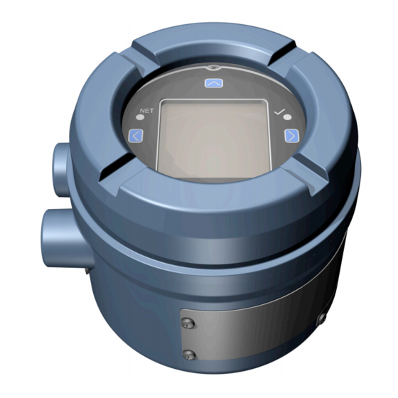
Installation Manual Components of the transmitter display 00825-0100-1600 March 2022 Components of the transmitter display The transmitter display includes two status LEDs, a multi-line LCD panel, and four membrane arrow keys — left, up, down, and right — used to access the display menus and navigate the display screens. -
Page 40: Access And Use The Display Menus
1. Observe the action bar at the bottom of the LCD panel. The action bar displays Menu⇨. 2. Press your thumb or finger over the ⇨ membrane switch to activate it. The top-level menu is displayed. Micro Motion 1600 Ethernet Transmitters... - Page 41 Installation Manual Components of the transmitter display 00825-0100-1600 March 2022 3. Navigate the menus using the four membrane switches: Activate ⇧ or ⇩ to scroll to the previous or next item in the menu. • Activate and hold ⇧ or ⇩ (approximately 1 second) to scroll rapidly through •...
- Page 42 If display security is enabled, the display prompts you to enter the display password. 5. If you make a menu choice that requires entering a numeric value or character string, the display provides a screen similar to the following: Micro Motion 1600 Ethernet Transmitters...
- Page 43 Installation Manual Components of the transmitter display 00825-0100-1600 March 2022 Figure 9-4: Numeric values and character strings Activate ⇦ or ⇨ to position the cursor. • Activate ⇧ and ⇩ to scroll through the values that are valid for that position. •...
- Page 44 Components of the transmitter display Installation Manual March 2022 00825-0100-1600 Micro Motion 1600 Ethernet Transmitters...
-
Page 45: Available Service Port Connection
Installation Manual Available service port connection 00825-0100-1600 March 2022 Available service port connection Use the service port connection to download or upload data from/to the transmitter. To access the service port, you can use the following signal converter to connect to the service port terminals: •... - Page 46 Available service port connection Installation Manual March 2022 00825-0100-1600 Micro Motion 1600 Ethernet Transmitters...
-
Page 47: Appendix A Wire The 1600 To The 3100 Relays
Installation Manual Wire the 1600 to the 3100 relays 00825-0100-1600 March 2022 Wire the 1600 to the 3100 relays Use this procedure to wire the Discrete Output on the 1600 Ethernet transmitter to the 3100 transmitter relays for single-stage batch control. Prerequisites •... - Page 48 © 2022 Micro Motion, Inc. All rights reserved. The Emerson logo is a trademark and service mark of Emerson Electric Co. Micro Motion, ELITE, ProLink, MVD and MVD Direct Connect marks are marks of one of the Emerson Automation Solutions family of companies.
Need help?
Do you have a question about the Micro Motion 1600 and is the answer not in the manual?
Questions and answers