Table of Contents
Advertisement
Description
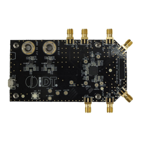
The 8V97003 evaluation board is designed to enable customers to
evaluate the functionality and performance of the 8V97003
RF/Microwave Wideband Synthesizer. The 8V97003 device on the
evaluation board can be programmed and configured via a PC-
based GUI, called Timing Commander, to generate output
frequency from 187.5MHz to 18GHz with very low phase noise and
RMS phase jitter.
This document discusses the setup of the EVB, and the
programming of the 8V97003 using Timing Commander.
Kit Contents
8V97003 Evaluation Board
Micro USB Cable
8V97003 Evaluation Board
© 2020 Renesas Electronics Corporation
Required Software
IDT Timing Commander Software Installer (available at
www.idt.com/timingcommander)
Network access during installation if the .NET framework
is not currently installed on the system
8V97003 GUI (available at www.idt.com/8V97003)
USB 2.0 or USB 3.0 interface
1
8V97003 EVB Manual
January 10, 2020
Advertisement
Table of Contents

Related Manuals for Renesas 8V97003


Summary of Contents for Renesas 8V97003
- Page 1 8V97003 EVB Manual Description Required Software The 8V97003 evaluation board is designed to enable customers to IDT Timing Commander Software Installer (available at evaluate the functionality and performance of the 8V97003 www.idt.com/timingcommander) RF/Microwave Wideband Synthesizer. The 8V97003 device on the Network access during installation if the .NET framework...
- Page 2 Ensure the correct connection of all cables. Supplying the board using the wrong polarity could result in damage to the board and/or the equipment. Check that all jumpers have been removed from the board before applying power. © 2020 Renesas Electronics Corporation January 10, 2020...
-
Page 3: Table Of Contents
Programming/Configuration ......................8 2.1 Opening an Existing Configuration ..............................8 2.2 Making Changes to an Existing Configuration ...........................10 2.3 Creating a New Configuration ................................11 Performance Evaluation with the 8V97003 EVB ............................12 3.1 Output Matching ....................................12 3.2 AC-coupling Capacitor ..................................13 3.3 Termination ......................................13 3.4 Transmission Line Loss ..................................13... - Page 4 Figure 8. “Locked” Settings View in “Bit Sets” Tab ............................10 Figure 9. New Settings GUI ....................................11 Figure 10. 8V97003 Output Power over Frequencies – Resistive vs. Inductive Matching .................12 Figure 11. Transmission Line Loss – 8V97003 EVB Revision D ........................14 Figure 12.
-
Page 5: Hardware Setup
Lock detect LED: LED indicator of PLL Lock status RF_OUTB/nRF_OUTB output SMA connectors: differential RF/Microwave outputs at J3, J4 RF_OUTA/nRF_OUTA output SMA connectors: differential RF/Microwave outputs at J1, J2 SYNC input: J16 © 2020 Renesas Electronics Corporation January 10, 2020... -
Page 6: Required Equipment
Signal Generator A signal generator is necessary to generate the reference clock to the 8V97003. A single-ended reference clock is connected to J6, while J8 can be left unconnected. When a differential reference clock is available, connect them to J6 and J8. -
Page 7: Hardware Connection
1. Turn the bench power supply on. Initial current consumption of the whole EVB should be around 500mA. 2. Set the reference clock input frequency and amplitude on the Signal Generator – enable Signal Generator output. 3. Program the 8V97003 using IDT’s Timing Commander GUI. © 2020 Renesas Electronics Corporation... -
Page 8: Working With Timing Commander
Starting Up Timing Commander GUI 3. At the “Open Settings File” dialog box, browse to select the setting file (*.tcs) and the personality file (*.tcp), then click “Open.” Figure 3. Open Settings File Dialog Box © 2020 Renesas Electronics Corporation January 10, 2020... -
Page 9: Figure 4. Connect To The 8V97003
Timing Commander (PC) and to set up the communication interface, click the “Connect” button (chip symbol) at the upper right corner of the GUI. The connection will be established if a valid 8V97003 is detected, and a green band appears at the upper right corner of the GUI window. Figure 4. -
Page 10: Making Changes To An Existing Configuration
A quick way to view all “Locked” settings in an existing configuration is to select “Locked” option in “Bit Sets” tab, as shown in Figure 8. Figure 8. “Locked” Settings View in “Bit Sets” Tab © 2020 Renesas Electronics Corporation January 10, 2020... -
Page 11: Creating A New Configuration
6. Once all settings have valid values, click the Connect button (chip symbol) at the upper right corner of the GUI to set up the communication interface. The connection will be established if a valid 8V97003 is detected, and a green band appears at the upper right corner of the GUI window. 7. Click “Write All” to program the 8V97003. -
Page 12: Performance Evaluation With The 8V97003 Evb
The 8V97003 provides two differential outputs of CML type. The outputs are “open collector outputs” and can be matched in different ways. By default, a simple resistive matching is used on the 8V97003 EVB. This resistive matching consists of a 50Ω resistor to VDD, with a series AC coupling capacitor. -
Page 13: Ac-Coupling Capacitor
3.2 AC-coupling Capacitor AC-coupling capacitors are populated on the 8V97003 EVB to ensure 0V DC on the output signals when they are connected to the input of (RF) measurement equipment. The part number of the (series) AC-coupling capacitor used on the 8V97003 EVB is 520L103KT16T, which is specified for operation up to 16GHz. -
Page 14: Figure 11. Transmission Line Loss - 8V97003 Evb Revision D
50Ω. This issue causes performance degradation in output power, harmonic, and phase noise. This trace loss should be considered if you are evaluating the 8V97003 RF/Microwave Synthesizer on IDT’s EVB Revision C. -
Page 15: Schematics
8V97003 EVB Manual 4. Schematics Figure 13. Evaluation Board Schematic – Page 1 © 2020 Renesas Electronics Corporation January 10, 2020... -
Page 16: Figure 14. Evaluation Board Schematic
8V97003 EVB Manual Figure 14. Evaluation Board Schematic – Page 2 © 2020 Renesas Electronics Corporation January 10, 2020... -
Page 17: Figure 15. Evaluation Board Schematic
8V97003 EVB Manual Figure 15. Evaluation Board Schematic – Page 3 © 2020 Renesas Electronics Corporation January 10, 2020... -
Page 18: Bill Of Materials (Bom)
LD1, LD2 LED_0603_1206_H Panasonic LNJ616C8WRA 600 ohm 500mA MMZ1608Y601B Corporation Murata L2, L3 18nH,0.4A,360mOhm LQG15HS18NJ02 Electronics NA FC0402E50R0BS R10, R15 0402M Vishay-Dale R7, R19, R26, R50, R51, R52, 0402M Panasonic ERJ-2GEJ102X 0402M © 2020 Renesas Electronics Corporation January 10, 2020... - Page 19 6MHz XTAL_5mmx7mm Corporation 6.000MHZ-B2-T C1, C5, C13, C14, C91, C92 10000pF AT Ceramics 520L103KT16T 0402M Panasonic ERJ-2GEJ200X 220nF 0402M U5, U7, R47, R46, R48, R44, R49, R45, C26, C27, C28, R54, R55 © 2020 Renesas Electronics Corporation January 10, 2020...
-
Page 20: Board Layout
Figure 16. Evaluation Board – Top Layer Figure 17. Evaluation Board – Second Layer Figure 18. Evaluation Board – Third Layer Figure 19. Evaluation Board – Bottom Layer 7. Ordering Information Contact Renesas Sales at https://www.idt.com/buy-sample/locations. © 2020 Renesas Electronics Corporation January 10, 2020... -
Page 21: Appendix A - New Configuration Examples
Example 1 – New Configuration for Integer Mode of Operation In this example, the Timing Commander GUI’s is used to create a new configuration for the 8V97003 with the following operating parameters: Input Reference Frequency: 245.76MHz; Input signal type: Differential ... -
Page 22: Figure 20. Timing Commander Gui For Creating New Integer Mode Configuration
8V97003 EVB Manual Figure 20. Timing Commander GUI for Creating New Integer Mode Configuration © 2020 Renesas Electronics Corporation January 10, 2020... -
Page 23: Figure 21. Expected Performance Of 8110.08Mhz Output From Example 1
8V97003 EVB Manual Figure 21. Expected Performance of 8110.08MHz Output from Example 1 © 2020 Renesas Electronics Corporation January 10, 2020... -
Page 24: Example 2 - New Configuration For Fractional Mode Of Operation
Example 2 – New Configuration for Fractional Mode of Operation In this example, the Timing Commander GUI is used to create a new configuration for the 8V97003 with the following operating parameters: Input reference frequency: 245.76MHz; Input signal type: Differential ... -
Page 25: Figure 22. Timing Commander Gui For Creating New Fractional Mode Configuration
8V97003 EVB Manual Figure 22. Timing Commander GUI for Creating New Fractional Mode Configuration © 2020 Renesas Electronics Corporation January 10, 2020... -
Page 26: Figure 23. Expected Performance Of 8200Mhz Output Without Bleeder Current From Example 2
8V97003 EVB Manual Figure 23. Expected Performance of 8200MHz Output without Bleeder Current from Example 2 © 2020 Renesas Electronics Corporation January 10, 2020... -
Page 27: Figure 24. Expected Performance Of 8200Mhz Output With 1.1Ma Of Bleeder Current From Example 2
8V97003 EVB Manual Figure 24. Expected Performance of 8200MHz Output with 1.1mA of Bleeder Current from Example 2 © 2020 Renesas Electronics Corporation January 10, 2020... -
Page 28: Appendix B - Input Reference Phase Noise Performance
Phase noise measurement results shown in Figure 21, Figure 23, and Figure 24 were obtained with the input reference clock from a bench signal generator. Because the in-band phase noise performance of the 8V97003 is dictated by the phase noise performance of the input reference, the input reference’s phase noise performance is provided below. -
Page 29: Revision History
8V97003 EVB Manual Revision History Revision Date Description of Change Rebranded the document as Renesas. No technical changes were made. January 10, 2020 Updated Figure 1 and added additional bullet (second bullet) to the board descriptions Updated Transmission Line Loss December 2, 2019 ... - Page 30 Renesas' products are provided only subject to Renesas' Terms and Conditions of Sale or other applicable terms agreed to in writing. No use of any Renesas resources expands or otherwise alters any applicable warranties or warranty disclaimers for these products.
Need help?
Do you have a question about the 8V97003 and is the answer not in the manual?
Questions and answers