Table of Contents
Advertisement
Quick Links
8V97003 EVB User Manual
Evaluation Board
The 8V97003 evaluation board is designed for customers to evaluate the functionality and performance of the
8V97003 RF/Microwave Wideband Synthesizer. On the evaluation board, the 8V97003 device can be
programmed and configured with Timing Commander, a PC-based GUI that generates output frequency from
187.5MHz to 18GHz with a very low phase noise and RMS phase jitter. This user manual details the setup of the
EVB and the programming of the 8V97003 using Timing Commander.
Contents
1.
Overview ......................................................................................................................................................... 3
2.
Functional Description .................................................................................................................................. 4
2.1
Evaluation Board Overview ................................................................................................................... 4
2.2
Required Equipment .............................................................................................................................. 5
2.2.1.
Power Supply .......................................................................................................................... 5
2.2.2.
Signal Generator ..................................................................................................................... 5
2.2.3.
Phase Noise Analyzer/Spectrum Analyzer ............................................................................. 5
2.2.4.
Balun ....................................................................................................................................... 5
2.2.5.
PC ........................................................................................................................................... 5
2.3
Hardware Connection ............................................................................................................................ 6
2.4
Power-up Procedures ............................................................................................................................ 6
3.
Working with Timing Commander™ for Programming/Configuration..................................................... 7
3.1
Opening an Existing Configuration ........................................................................................................ 7
3.2
Making Changes to an Existing Configuration ...................................................................................... 9
3.3
Creating a New Configuration ............................................................................................................. 10
4.
Performance Evaluation with the 8V97003 EVB ....................................................................................... 11
4.1
Output Matching .................................................................................................................................. 11
4.2
AC-coupling Capacitor ......................................................................................................................... 12
4.3
Termination .......................................................................................................................................... 12
4.4
Transmission Line Loss ....................................................................................................................... 12
5.
PCB Layout Guidelines ............................................................................................................................... 14
5.1
8V97003 Evaluation Board Schematic ................................................................................................ 14
6.
Bill of Materials (BOM) ................................................................................................................................ 17
7.
Board Layout ................................................................................................................................................ 18
8.
Ordering Information ................................................................................................................................... 20
9.
Revision History .......................................................................................................................................... 20
Appendix A - New Configuration Example ....................................................................................................... 21
Appendix B - Input Reference Phase Noise Performance .............................................................................. 28
Rev.1.2
Sep.25.20
User Manual
Page 1
Advertisement
Table of Contents

Subscribe to Our Youtube Channel
Related Manuals for Renesas 8V97003


Summary of Contents for Renesas 8V97003
-
Page 1: Table Of Contents
8V97003 EVB User Manual Evaluation Board The 8V97003 evaluation board is designed for customers to evaluate the functionality and performance of the 8V97003 RF/Microwave Wideband Synthesizer. On the evaluation board, the 8V97003 device can be programmed and configured with Timing Commander, a PC-based GUI that generates output frequency from 187.5MHz to 18GHz with a very low phase noise and RMS phase jitter. - Page 2 Figure 9. Locked Settings View in Bit Sets Tab......................9 Figure 10. New Settings GUI ..........................10 Figure 11. 8V97003 Output Power Over Frequencies – Resistive vs. Inductive Matching ........11 Figure 12. 8V97003 EVB Revision D Transmission Line Loss ................13 Figure 13. 8V97003 EVB Revision C Transmission Line Loss ................13 Figure 14.
-
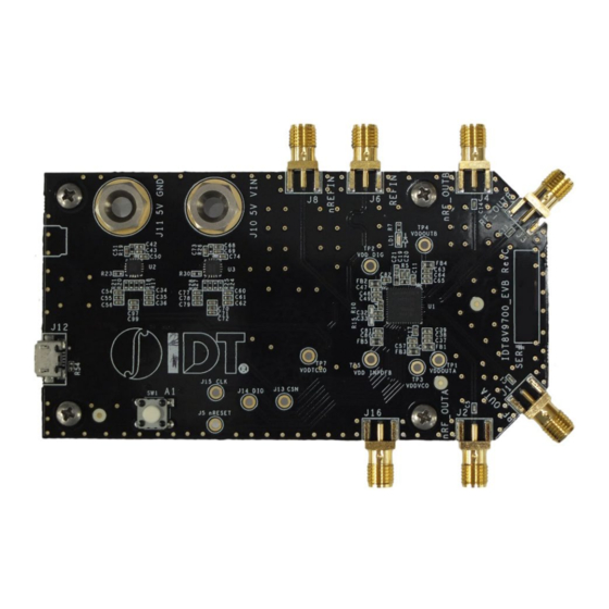
Page 3: Overview
8V97003 EVB User Manual Overview Figure 1. 8V97003 EVB – Top View Kit Contents 8V97003 Evaluation Board • Micro USB cable • Required Software IDT Timing Commander Software Installer (available at www.idt.com/timingcommander) • Network access during installation if the .NET framework is not currently installed on the system •... -
Page 4: Functional Description
8V97003 EVB User Manual Functional Description This section provides an overview of the different components on the evaluation board, and discusses the necessary bench equipment, the hardware connection, and the power-up sequence. Evaluation Board Overview The following diagram identifies various components of the board: power supply jacks, input and output SMA connectors, USB interface port, and lock indicator LED. -
Page 5: Required Equipment
Balun is optional. A balun is used to convert single-ended output of a signal generator to differential output, which is used to provide reference clock to the 8V97003 RF/Microwave Synthesizer. Another balun can be used to combine the differential outputs of the 8V97003 to a single-ended signal for measurement with a phase noise analyzer/spectrum analyzer. -
Page 6: Hardware Connection
1. Turn bench power supply on. Initial current consumption of the whole EVB should be around 500mA 2. Set reference clock input frequency and amplitude on Signal Generator – enable Signal Generator output 3. Program 8V97003 RF/Microwave Synthesizer using IDT’s Timing Commander GUI Rev.1.2 Page 6 Sep.25.20... -
Page 7: Working With Timing Commander™ For Programming/Configuration
8V97003 EVB User Manual Working with Timing Commander™ for Programming/Configuration Opening an Existing Configuration When a customer’s user case information is provided to IDT prior to EVB is sampled, an optimized configuration is usually provided to the customer for the evaluation. Follow the procedure below to open a setting file: 1. -
Page 8: Figure 5. Connect To 8V97003 Device
GUI to set up the communication interface. Figure 5. Connect to 8V97003 Device 5. The connection will be established if a valid 8V97003 is detected, and a green band appears at the upper right corner of the GUI window. -
Page 9: Making Changes To An Existing Configuration
8V97003 EVB User Manual Making Changes to an Existing Configuration When changes to an existing configuration is necessary, make sure none of the settings in the affected signal path is locked as to allow the GUI to make appropriate calculation for optimal settings. A locked setting is indicated by a white lock symbol in a red box ( ). -
Page 10: Creating A New Configuration
6. Once all settings have valid values, click the Connect button (chip symbol) at the upper right corner of the GUI to set up the communication interface. 7. The connection will be established if a valid 8V97003 is detected, and a green band appears at the upper right corner of the GUI window. -
Page 11: Performance Evaluation With The 8V97003 Evb
The 8V97003 devices provides two differential outputs of CML type. The outputs are “open collector outputs” and can be matched in different ways. By default, a simple resistive matching is used on the 8V97003 EVB. This resistive matching consists of a 50Ω resistor to VDD, with a series AC coupling capacitor. This matching scheme gives the output amplitude a “broadband”... -
Page 12: Ac-Coupling Capacitor
(if applicable), loss across frequencies due to transmission line on the EVB must also be characterized. To assist customer with the measurement of trace loss on 8V97003 EVB, a test “coupon” is included in the same PCB manufacturing panel with the main EVB. This test “coupon” consists of the exact copy of the transmission lines on the board and the SMA connectors. -
Page 13: Figure 12. 8V97003 Evb Revision D Transmission Line Loss
50Ω. This issue causes performance degradation in output power, harmonic, and phase noise. If you are evaluating the 8V97003 RF/Microwave Synthesizer on IDT’s EVB revision C, this trace loss should be taken into account. -
Page 14: Pcb Layout Guidelines
8V97003 EVB User Manual PCB Layout Guidelines 8V97003 Evaluation Board Schematic Figure 14. Schematic - Page 1 Rev.1.2 Page 14 Sep.25.20... -
Page 15: Figure 15. Schematic
8V97003 EVB User Manual Figure 15. Schematic - Page 2 Rev.1.2 Page 15 Sep.25.20... -
Page 16: Figure 16. Schematic
8V97003 EVB User Manual Figure 16. Schematic - Page 3 Rev.1.2 Page 16 Sep.25.20... -
Page 17: Bill Of Materials (Bom)
8V97003 EVB User Manual Bill of Materials (BOM) Item Reference Part PCB Footprint Manufacturer Part Number C2,C3,C4,C6,C7,C8,C9,C10,C32, C33,C35,C39,C40,C41,C42,C49, C52,C53,C55,C59,C61,C65,C66, 0.1u 0402M Murata Electronics NA GRM155R61A104KA01D C67,C68,C71,C75,C76,C78,C82, C83,C85,C87,C96,C99 C11,C12,C36,C56,C62,C72,C79,C86 0.01u 0402M Taiyo Yuden EMK105B7103KV-F C15,C17,C22,C24,C26 0402M 2.2nF 0402M 680pF 0402M 47nF... -
Page 18: Board Layout
8V97003 EVB User Manual Board Layout Figure 17. Evaluation Board – Top Layer Figure 18. Evaluation Board – Second Layer Rev.1.2 Page 18 Sep.25.20... -
Page 19: Figure 19. Evaluation Board - Third Layer
8V97003 EVB User Manual Figure 19. Evaluation Board – Third Layer Figure 20. Evaluation Board – Bottom Layer Rev.1.2 Page 19 Sep.25.20... -
Page 20: Ordering Information
8V97003 EVB User Manual Ordering Information Contact Renesas Sales at https://www.renesas.com/support.html. Revision History Revision Date Description Updated the formatting. Sep.25.20 Completed minor changes throughout. Oct.22.19 Initial release. Nov.15.19 Rev.1.2 Page 20 Sep.25.20... -
Page 21: Appendix A - New Configuration Example
Appendix A – New Configuration Example Example 1 – New Configuration for Integer Mode of Operation In this example, we will use Timing Commander GUI to create a new configuration for 8V97003 RF/Microwave Synthesizer device with the following operating parameters: Input reference frequency: 245.76MHz –... -
Page 22: Figure 21. Timing Commander Gui For Creating New Integer Mode Configuration
8V97003 EVB User Manual Figure 21. Timing Commander GUI for Creating New Integer Mode Configuration Rev.1.2 Page 22 Sep.25.20... -
Page 23: Figure 22. Expected Performance Of 8110.08Mhz Output From Example 1
8V97003 EVB User Manual Figure 22. Expected Performance of 8110.08MHz Output from Example 1 Rev.1.2 Page 23 Sep.25.20... - Page 24 8V97003 EVB User Manual Example 2 – New Configuration for Fractional Mode of Operation In this example, we will use Timing Commander GUI to create a new configuration for 8V97003 RF/Microwave Synthesizer device with the following operating parameters: Input reference frequency: 245.76MHz – Input signal Type: Differential •...
-
Page 25: Figure 23. Timing Commander Gui For Creating New Fractional Mode Configuration
8V97003 EVB User Manual Figure 23. Timing Commander GUI for Creating New Fractional Mode Configuration Rev.1.2 Page 25 Sep.25.20... -
Page 26: Figure 24. Expected Performance Of 8200Mhz Output Without Bleeder Current From Example 2
8V97003 EVB User Manual Figure 24. Expected Performance of 8200MHz Output without Bleeder Current from Example 2 Rev.1.2 Page 26 Sep.25.20... -
Page 27: Figure 25. Expected Performance Of 8200Mhz Output With 1.1Ma Of Bleeder Current From Example 2
8V97003 EVB User Manual Figure 25. Expected Performance of 8200MHz Output with 1.1mA of Bleeder Current from Example 2 Rev.1.2 Page 27 Sep.25.20... -
Page 28: Appendix B - Input Reference Phase Noise Performance
Phase noise measurement results shown in Figure 22, Figure 24, and Figure 25 were obtained with the input reference clock from a bench signal generator. Because the in-band phase noise performance of 8V97003 RF/Microwave Synthesizer is dictated by the phase noise performance of the input reference, the input reference’s phase noise performance is provided in Figure 26. - Page 29 Renesas' products are provided only subject to Renesas' Terms and Conditions of Sale or other applicable terms agreed to in writing. No use of any Renesas resources expands or otherwise alters any applicable warranties or warranty disclaimers for these products.
Need help?
Do you have a question about the 8V97003 and is the answer not in the manual?
Questions and answers