Table of Contents
Advertisement
Quick Links
Description
The 8Axxxx 48QFN EVK is designed to help customers evaluate
IDT ClockMatrix devices. This document discusses the following
about the EVK:
Introduces the board and its power supply and jumper settings
Describes the input and output connectors for normal
operation
Explains how to bring up the board using the Timing
Commander software GUI
Discusses how to configure and program the board to
generate standard-compliant frequencies
Kit Contents
8A34xxx 48QFN Evaluation Board
USB Type A cable
8A3xxxx 48QFN EVK Board
© 2019 Integrated Device Technology, Inc.
8A3xxxx 48QFN EVK User Manual
Requirements
IDT Timing Commander Software Installed (available at
www.idt.com/timingcommander)
ClockMatrix GUI (available at www.idt.com/clockmatrix)
USB 2.0 or USB 3.0 interface
Windows XP SP3 or later
Processor: Minimum 1GHz
Memory: Minimum 512MB; recommended 1GB
Available disk space: Minimum 600MB (1.5GB 64-bit);
recommended 1GB (2GB 64-bit)
Network access during installation if the .NET framework is not
currently installed on the system
1
February 15, 2019
Advertisement
Table of Contents

Subscribe to Our Youtube Channel
Related Manuals for Renesas 8A34 48QFN Series


Summary of Contents for Renesas 8A34 48QFN Series
- Page 1 8A3xxxx 48QFN EVK User Manual Description Requirements The 8Axxxx 48QFN EVK is designed to help customers evaluate IDT Timing Commander Software Installed (available at IDT ClockMatrix devices. This document discusses the following www.idt.com/timingcommander) about the EVK: ClockMatrix GUI (available at www.idt.com/clockmatrix) ...
-
Page 2: Table Of Contents
8A3xxxx 48QFN EVK User Manual Important Notes Disclaimer Integrated Device Technology, Inc. and its affiliated companies (herein referred to as “IDT”) shall not be liable for any damages arising out of defects resulting from delivered hardware or software (ii) non-observance of instructions contained in this manual and in any other documentation provided to user, or (iii) misuse, abuse, use under abnormal conditions, or alteration by anyone other than IDT. - Page 3 8A3xxxx 48QFN EVK User Manual List of Figures Figure 1. Overview of 48QFN ClockMatrix Evaluation Board ..........................4 Figure 2. Example of Voltage Jumpers ................................5 Figure 3. GPIO Setting and Status Display Area ..............................7 Figure 4. Board Setting for Default Operation ..............................9 Figure 5.
-
Page 4: Usage Guide
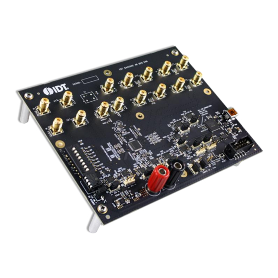
8A3xxxx 48QFN EVK User Manual 1. Usage Guide 1.1 Board Overview The following diagram identifies various components of the board: input and output SMA connectors, power supply jacks, and some jumper settings necessary for the board operations. Figure 1. Overview of 48QFN ClockMatrix Evaluation Board Detailed descriptions of the board are as follows. -
Page 5: Board Power Supply
8A3xxxx 48QFN EVK User Manual VCCO voltage selection jumpers – Each output voltage can be individually supplied with 1.8V, 2.5V, or 3.3V. These jumpers are used to select the voltage for the output voltages. Reset button – A small button is used to reset the board. ... -
Page 6: Gpio Switches, Leds, And Test Points
8A3xxxx 48QFN EVK User Manual The following list shows which header/jumper is used to select what voltage: JP1 – VDDD JP2 – VDDA JP3 – VCC_GPIO_DC JP4 – VDDO_Q8_3_5 JP5 – VDDO_Q2_4_11 JP6 – VDDO_1_10_7 ... -
Page 7: Usb Jack
8A3xxxx 48QFN EVK User Manual Figure 3. GPIO Setting and Status Display Area 1.5 USB Jack The board has a USB mini-connector. The other end of the USB cable is a USB Type A connector going to a PC. 1.6 Onboard EEPROM An onboard EEPROM is used to store device firmware and/or customer’s configuration data. -
Page 8: Working With Timing Commander™ For Programing/Configuration
8A3xxxx 48QFN EVK User Manual 2. Working with Timing Commander™ for Programing/Configuration The following sections are best cross-referenced with the ClockMatrix GUI Step-by-Step User Guide which is available on www.idt.com. 2.1 Default Operation The board can operate off an EEPROM that has stored all information including firmware and a default configuration data. A default operation provides a sanity check on the board before running the board through the IDT Timing Commander. -
Page 9: Figure 4. Board Setting For Default Operation
8A3xxxx 48QFN EVK User Manual Figure 4. Board Setting for Default Operation Important Equipment Warning: In order to set GPIO8 and GPIO9 to “High”, the switches for GPIO8 and GPIO9 must be set either to the “+” (high) position or the center position. ©... -
Page 10: Using Timing Commander To Control The Board
8A3xxxx 48QFN EVK User Manual 2.2 Using Timing Commander to Control the Board Once the default operation is successful, complete the following steps to configure and program the ClockMatrix device per your specific application requirements using Timing Commander GUI tools: 1. -
Page 11: Figure 6. Selecting 8A34001 Using Personality File V4.6
8A3xxxx 48QFN EVK User Manual 3. After selecting “New Settings File”, a device selection window will pop up. In the window, choose the intended device in the list (in this example, 8A34001 is selected). Click the button at the lower right corner of the window (red circle) to browse and select the correct personality file (in this example, personality v4.6 is selected). -
Page 12: Figure 7. Timing Commander Gui With A Settings File Opened
8A3xxxx 48QFN EVK User Manual 4. The GUI window with the 8A34001 block diagram will open for configurations; or if “Open Settings File” is selected in Step 3, you will be prompted to browse and select an existing .tcs file and the personality file. When the configuration file is open, all configured values will be displayed (see Figure 7). -
Page 13: Figure 8. Setting I 2 C For Connecting The Board With Gui
8A3xxxx 48QFN EVK User Manual 5. In order to connect the board with Timing Commander (PC), click the button (red circle) at the up-right corner of the GUI to set up the communication protocols (see Figure 7). After I C and one-byte addressing are selected, click OK to close the window. Figure 8. -
Page 14: Figure 10. Firmware Version Mismatch Warning Message
8A3xxxx 48QFN EVK User Manual 7. If ClockMatrix chip’s firmware, or firmware loaded from EEPROM, has a different version from that in the Personality file, a firmware version mismatch warning message will appear. Click “Close” button to close the message window and a connection is made. Figure 10. -
Page 15: Figure 12. Read Firmware Version Of Clockmatrix Chip
8A3xxxx 48QFN EVK User Manual 9. Within the Firmware Utility window, click the “Get Firmware Version” button to read the firmware version. Figure 12. Read Firmware Version of ClockMatrix Chip 10. In the case where the firmware version mismatches each other, a firmware upgrade is necessary to update the chip’s firmware. To do so, complete the steps in How to Upgrade the Firmware to update the chip’s firmware. -
Page 16: Output Terminations And Rework To Take 1Pps Input
8A3xxxx 48QFN EVK User Manual 2.3 Output Terminations and Rework to Take 1PPS Input All outputs are terminated per LVDS with a 100Ω resistor across the output pair. When the output is configured as PECL2.5 and PECL3.3 or user-defined differential, the output clock will still be switching. The amplitude may be different from expected until the hardware termination matches the signaling type configured for the output. -
Page 17: How To Upgrade The Firmware
8A3xxxx 48QFN EVK User Manual 3. How to Upgrade the Firmware 3.1 Upload Firmware to the RAM 1. Connect to the EVK board. 2. Power up the board with no EEPROM present. This ensures the firmware is 4.0.2.7017, as displayed in the figure. 3. - Page 18 8A3xxxx 48QFN EVK User Manual In the next window, press “Yes” and wait around 3-4 minutes. Once the firmware is updated, the following window will indicate a successful update. Click “Close”. Press “Get Firmware Version” to verify that the RAM was updated correctly, then click “Close”. ©...
-
Page 19: Upload Firmware Into The Eeprom
8A3xxxx 48QFN EVK User Manual 3.2 Upload Firmware into the EEPROM 1. Once the firmware has been updated to the chip (steps 1 to 8), install the EEPROM on the EVK board. 2. Press “Write Firmware to EEPROM Only”. 3. In the next window, press “Yes”. ©... -
Page 20: Verify The Eeprom Programming
8A3xxxx 48QFN EVK User Manual 4. When asked to “Verify” the EEPROM, press “No”. 5. In the next window, press “Close” to start the EEPROM write. 6. Wait about 5 minutes for the EEPROM write to complete. Click “Close” in the following window. 3.3 Verify the EEPROM Programming 7. -
Page 21: Schematics
8A3xxxx 48QFN EVK User Manual 4. Schematics Please see the schematics located at the end of this document. 5. Ordering Information Orderable Part Number Description 8A34043-EVK 8A3xxxx 48QFN Evaluation Kit 6. Revision History Revision Date Description of Change February 15, 2019 Initial release. - Page 23 C418 2200pF C763 0.1uF C762 0.1uF C761 10uF R467 2.67k R910 2.67k R466 49.9 C713 0.1uF...
- Page 24 52.3k R707 52.3k 0.01uF C867 0.01uF 1.0uF 1.0uF C866 R703 Stuff for 3.3V R909 R908 R597 Stuff for 2.5V R599 17.4k R598 10k R907 52.3k 52.3k C836 1000pF C837 10uF R486 C846 C845 C957 0.01uF 0.01uF C956 1.0uF 1.0uF RvR 19-11-14 BZX84C5V6 R902 DIODE ZENER 5.6V 350MW SOT23-3...
- Page 25 R406 52.3k 52.3k 0.01uF 0.01uF C406 1.0uF 1.0uF C405 R400 52.3k 52.3k 52.3k 0.01uF 0.01uF 0.01uF 1.0uF 1.0uF 1.0uF...
- Page 26 C411 0.1uF C413 0.1uF C410 0.1uF C412 0.1uF R423 R422 R421 4.7k R420 4.7k R419 4.7k R418 4.7k R385 3.3uF 0.1uF C691 0.1uF 12pF 0.1uF 0.1uF 0.1uF 0.1uF 0.1uF 0.1uF 0.1uF 0.1uF 4.7uF 4.7uF C684 C685 C690 12pF R474 C688 10uF R384 R383...
- Page 28 R443 C416 0.1uF R442 C415 0.1uF R935 4.7k R444 R445 C426 0.01uF R446 4.7k R447 4.7k R448 4.7k R450 R453 4.7k R451 4.7k R454 4.7k R473 R452 4.7k R455 4.7k C417 0.1uF...
- Page 29 R776 2.67k R771 2.67k R460 2.67k R782 2.67k 2.67k 2.67k 2.67k 2.67k R765 R770 R775 R781 C196 0.1uF C195 10uF C844 0.1uF...
- Page 30 R734 R743 R752 R761...
- Page 31 C9520.1uF C95110uF C871 0.1uF C732 0.1uF C695 0.1uF C731 10uF C694 0.1uF C693 0.1uF C692 10uF C9400.1uF C722 0.1uF C9460.1uF C93910uF C721 10uF C94510uF C959 0.1uF C958 0.1uF C726 0.1uF C734 0.1uF C730 0.1uF C725 10uF C733 10uF C729 10uF C698 0.1uF C8720.1uF...
- Page 32 Renesas' products are provided only subject to Renesas' Terms and Conditions of Sale or other applicable terms agreed to in writing. No use of any Renesas resources expands or otherwise alters any applicable warranties or warranty disclaimers for these products.
- Page 33 Mouser Electronics Authorized Distributor Click to View Pricing, Inventory, Delivery & Lifecycle Information: Renesas Electronics 8A34043-EVK...
Need help?
Do you have a question about the 8A34 48QFN Series and is the answer not in the manual?
Questions and answers