
Related Manuals for Renesas 8V9705 Series


Summary of Contents for Renesas 8V9705 Series
- Page 1 APPLICATION NOTE Network Communications Division 8V9705x Evaluation Board User Guide IDT Applications October 2016...
-
Page 2: Table Of Contents
8V9705x Rev C EVB Evaluation Board User Guide October 2016 Contents Introduction ............................3 Contents ............................. 3 Requirements ............................3 Quick Start ............................3 Default Power-Up Condition ........................ 3 Board Overview ..........................4 Schematics ............................7 ... -
Page 3: Introduction
8V9705x Rev C EVB Evaluation Board User Guide October 2016 Introduction The 8V9705x evaluation board is designed to help the customer evaluate the 8V97051, 8V97051L, 8V97053 and 8V97053L IDT Wideband RF synthesizers. When the board is connected to a PC running IDT Timing Commander Software through USB, the device can be configured and programmed to generate frequencies with best-in-class performances. -
Page 4: Board Overview
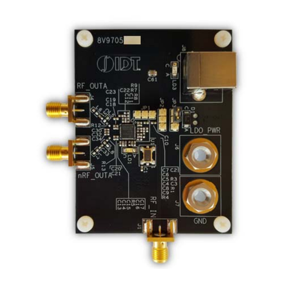
8V9705x Rev C EVB Evaluation Board User Guide October 2016 Board Overview Use the following diagram to identify: power supply jacks, USB connector, input and output SMA connectors, TCXO, etc. Figure 1. Evaluation Board Top View RF_OUTA RF_IN REVISION 1.1 10/19/2016... - Page 5 8V9705x Rev C EVB Evaluation Board User Guide October 2016 Legend Inputs RF_IN Reference input (the board requires re-work to enable this option) Outputs RF_OUTA Open-drain, ac-coupled output. Other IDT8V9705x- the device to be evaluated USB connector (also powers the board) 25 MHz TXCO (default reference source) External LDO_POWER (alternate power source) MUTE control (can be left floating)
-
Page 6: Figure 2. Evaluation Board Bottom View
8V9705x Rev C EVB Evaluation Board User Guide October 2016 Figure 2. Evaluation Board Bottom View Legend FTDI USB-to-I2C chip USB-to-SPI translator REVISION 1.1 10/19/2016... -
Page 7: Schematics
8V9705x Rev C EVB Evaluation Board User Guide October 2016 Schematics The following figures are schematics that are applicable to specific sections of this User Guide. The complete schematics are available in a separate document. Figure 3. Input Schematic Figure 4. Output Termination Schematic REVISION 1.1 10/19/2016... -
Page 8: Figure 5. Loop Filter Schematic
8V9705x Rev C EVB Evaluation Board User Guide October 2016 Figure 5. Loop Filter Schematic Figure 6 . Power Source Selection Schematic REVISION 1.1 10/19/2016... -
Page 9: Figure 7. Ldo Power Schematic
8V9705x Rev C EVB Evaluation Board User Guide October 2016 Figure 7. LDO Power Schematic Figure 8. I2C-to-SPI Translation Schematic REVISION 1.1 10/19/2016... -
Page 10: Powering From An External Supply
8V9705x Rev C EVB Evaluation Board User Guide October 2016 Figure 9. 8V9705x DUT Schematic Powering from an External Supply The evaluation board is by default configured to power through USB. (See JP3 jumper position in Fig. 1). To power the device from an external supply: 1) Set JP3 to the position shown in Figure 9. -
Page 11: External Signal Reference Configuration
8V9705x Rev C EVB Evaluation Board User Guide October 2016 External Signal Reference Configuration An on-board 25MHz TXCO provides the default source for RF_IN. In order to evaluate the device using an external signal reference, the following changes must be implemented: 1) Remove R20. - Page 12 8V9705x Rev C EVB Evaluation Board User Guide October 2016 CORPORATE for SALES: for Tech Support: 1-800-345-7015 or email: clocks@idt.com HEADQUARTERS 6024 Silver Creek Valley 408-284-8200 Road fax: 408-284-2775 San Jose, CA 95138 USA www.idt.com DISCLAIMER Integrated Device Technology, Inc. (IDT) and its subsidiaries reserve the right to modify the products and/or specifications described herein at any time and at IDT’s sole discretion.
- Page 13 Renesas' products are provided only subject to Renesas' Terms and Conditions of Sale or other applicable terms agreed to in writing. No use of any Renesas resources expands or otherwise alters any applicable warranties or warranty disclaimers for these products.
Need help?
Do you have a question about the 8V9705 Series and is the answer not in the manual?
Questions and answers