
Related Manuals for Pentair Hydromatic SHEF50S


Summary of Contents for Pentair Hydromatic SHEF50S
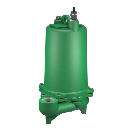
- Page 1 SUBMERSIBLE EFFLUENT PUMPS SHEF50S SHEF100S INSTALLATION & OPERATION MANUAL pentair.com ©2022 Pentair. All Rights Reserved.
-
Page 2: Table Of Contents
TABLE OF CONTENTS Safety Instructions ....................................3 Description ......................................4 Installation .......................................5 Diagrams .........................................6 Maintenance ......................................9 Specifications ......................................11 Repair Parts List ....................................14 Warranty ........................................ 16 056255661 (02-01-22) -
Page 3: Safety Instructions
SAFETY INSTRUCTIONS SAFETY SYMBOLS ELECTRICAL SAFETY Hazardous voltage. Can shock, burn, or kill. DANGER This is the safety alert symbol. When you see this symbol When installing, operating, or servicing this pump, follow the on your pump or in this manual, look for one of the following safety instructions listed below. -
Page 4: Description
The SHEF50S model impeller is an enclosed two vane type to Breathing hazard. Basin or tank must be vented in handle ¾” spherical solids and are available made of engineered accordance with local plumbing codes. -
Page 5: Installation
INSTALLATION A full flow (ball or gate) shut off valve must be installed to prevent back flow of effluent if the pump must be removed for POINTS TO CHECK IF PUMP DOES NOT RUN OR DOES NOT RUN service. A check valve must be installed on pressure sewer PROPERLY systems and on other systems where conditions allow to Pump does not run or start when water is up in tank. -
Page 6: Diagrams
DIAGRAMS 30” Diameter Simplex SHEF50S/SHEF100S 1/2 HP & 1 HP with Rail System 45º RAIL SUPPORT CONTROL MOUNTING BRACKET, SST JUNCTION BOX 30” DIA. BASIN COVER STRUCT. PLASTIC VALVE EXTENSION HANDLE As Req’d. 1-1/2” CONDUIT REQ’D. LIFT-OUT ROPE AS REQ’D. - Page 7 DIAGRAMS 30” Diameter Simplex Union System SHEF50S/SHEF100S 1/2 HP & 1 HP 45º CONTROL MOUNTING BRACKET, SST JUNCTION BOX 30” DIA. BASIN COVER STRUCT. PLASTIC 2” UNION, PVC 1-1/2” CONDUIT 2” GATE VALVE, REQ’D. BRASS AS REQ’D. LIFT-OUT ROPE AS REQ’D.
- Page 8 DIAGRAMS 48” Diameter Duplex SHEF50S/SHEF100S 1/2 HP & 1 HP CONTROL MOUNTING BRACKET, SST RAIL SUPPORT 45º 48” BASIN COVER W/HINGED HATCH JUNCTION BOX & LOCK HASP EPOXY COATED 1/4” STEEL STRUCT. PLASTIC VALVE EXTENSION HANDLE AS REQ’D. 2” CONDUIT REQ’D.
-
Page 9: Maintenance
MAINTENANCE BEFORE DISMANTLING PUMP FOR REPLACEMENT OF PARTS Replace with proper cord with fittings. Push cord into the motor housing far enough to make proper connections. Reconnect Clean pump thoroughly. Knock off all scale and deposits. Use ground wire if replacing power cord and securely connect the sandblast if possible. - Page 10 MAINTENANCE Remove snap ring with snap ring pliers. Pry off upper seal WIRING DIAGRAM bellows and ceramic seat. If no water has entered motor housing (check winding with BLACK ohmmeter or megger) wipe seal chambers thoroughly and WHITE replace seals. Clean seal faces and use light oil on face GREEN before installing bellows part of seal.
-
Page 11: Specifications
100 110 120 130 SHEF50SM1 20 CAPACITY GALLONS PER MINUTE SHEF50SM2 20 SHEF50SM5 20 DIMENSIONS SERIES DIMENSIONS INCHES (MILIMETERS) MODEL SERIES SHEF50S 16.8 (427) 4.09 1.03 12.13 SHEF100s 16.8 (427) 4.00 1.06 12.5 11.47 (291) 5.12 (130) 2”... - Page 12 SPECIFICATIONS MOTOR DATA CHART WINDING RESISTANCE IN OHMS START - 1Ø LOCKED MAIN H.P. SPEED VOLTS PHASE STACK HEIGHT BRN. TO BRN. OR MAX. AMPS WHITE TO ROTOR AMPS BLACK TO PURPLE WHITE BLACK TO RED - 3Ø .9/.8 14.7 12.1 29.6 1-5/8...
- Page 13 PAGE INTENTIONALLY LEFT BLANK 056255661 (02-01-22)
-
Page 14: Repair Parts List
REPAIR PARTS LIST OIL LEVEL 2” NPT 056255661 (02-01-22) - Page 15 REPAIR PARTS LIST REF. DESCRIPTION QTY. PART NUMBERS Nut, cord plug, solid 25341A002 Washer, 1/32” Thk. 05030A234 Gasket, Rubber 05014A193 Washer, 3/32” Thk. 05030A235 Plug, 1/4” pipe 05022A009 Cord, Power See Chart Screw, drive 05160A004 Name Plate Housing, Motor 25327D000 Capacitor (1Ph only) See Chart Clip, capacitor (1 Ph only)
-
Page 16: Warranty
Pentair Hydromatic will cover only the lower seal and labor thereof for all dual seal pumps. under no circumstance will Pentair Hydromatic be responsible for the cost of field labor, travel expenses, rented equipment, removal/reinstallation costs or freight expenses to and from the factory or an authorized Pentair Hydromatic service facility.
Need help?
Do you have a question about the SHEF50S and is the answer not in the manual?
Questions and answers