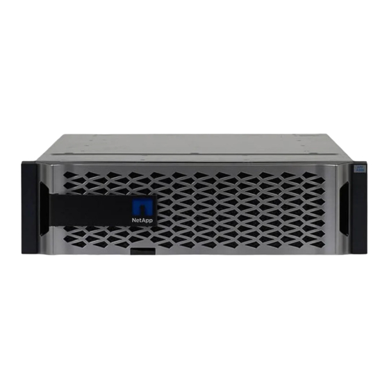
NetApp AFF A300 Manual
Hide thumbs
Also See for AFF A300:
- Manual (115 pages) ,
- System documentation (1672 pages) ,
- Install (314 pages)
Summary of Contents for NetApp AFF A300
- Page 1 Chassis ONTAP Systems NetApp May 13, 2022 This PDF was generated from https://docs.netapp.com/us-en/ontap-systems/a300/chassis-replace- overview.html on May 13, 2022. Always check docs.netapp.com for the latest.
-
Page 2: Table Of Contents
Shut down the controllers - - AFF A300 ............ -
Page 3: Chassis
• This procedure is written with the assumption that you are moving the controller module or modules to the new chassis, and that the chassis is a new component from NetApp. • This procedure is disruptive. For a two-node cluster, you will have a complete service outage and a partial outage in a multi-node cluster. - Page 4 About this task • If you are using NetApp Storage Encryption, you must have reset the MSID using the instructions in the "Return a FIPS drive or SED to unprotected mode" section of NetApp Encryption overview with the CLI.
- Page 5 If the impaired controller… Then… Has not automatically switched Perform a planned switchover operation from the healthy controller: over metrocluster switchover Has not automatically switched Review the veto messages and, if possible, resolve the issue and try over, you attempted switchover again.
-
Page 6: Replace Hardware - Aff A300
Errors: - 8. On the impaired controller module, disconnect the power supplies. Replace hardware - AFF A300 Move the power supplies, fans, and controller modules from the impaired chassis to the new chassis, and swap out the impaired chassis from the equipment rack or system cabinet with the new chassis of the same model as the impaired chassis. - Page 7 Power supply Cam handle release latch Power and Fault LEDs Cam handle...
- Page 8 Power cable locking mechanism 4. Use the cam handle to slide the power supply out of the system. When removing a power supply, always use two hands to support its weight. 5. Repeat the preceding steps for any remaining power supplies. 6.
- Page 9 Cam handle Fan module Cam handle release latch Fan module Attention LED 3. Pull the fan module straight out from the chassis, making sure that you support it with your free hand so that it does not swing out of the chassis. The fan modules are short.
- Page 10 10. Align the bezel with the ball studs, and then gently push the bezel onto the ball studs. Step 3: Remove the controller module To replace the chassis, you must remove the controller module or modules from the old chassis. 1.
- Page 11 Step 4: Replace a chassis from within the equipment rack or system cabinet You must remove the existing chassis from the equipment rack or system cabinet before you can install the replacement chassis. 1. Remove the screws from the chassis mount points. If the system is in a system cabinet, you might need to remove the rear tie-down bracket.
-
Page 12: Restore And Verify The Configuration - Aff A300
Ctrl-C repeat this step. b. From the boot menu, select the option for Maintenance mode. Restore and verify the configuration - AFF A300 You must verify the HA state of the chassis and run System-Level diagnostics, switch... - Page 13 NetApp, as described in the RMA instructions shipped with the kit. Step 1: Verify and set the HA state of the chassis You must verify the HA state of the chassis, and, if necessary, update the state to match your system configuration.
- Page 14 b. After the controller boots to Maintenance mode, halt the controller: halt After you issue the command, you should wait until the system stops at the LOADER prompt. During the boot process, you can safely respond to prompts: 2. Repeat the previous step on the second controller if you are in an HA configuration. Both controllers must be in Maintenance mode to run the interconnect test.
- Page 15 If the system-level diagnostics Then… tests… Were completed without any a. Clear the status logs: sldiag device clearstatus failures b. Verify that the log was cleared: sldiag device status The following default response is displayed: SLDIAG: No log messages are present. c.
- Page 16 If your system is running Then… ONTAP… Resulted in some test failures Determine the cause of the problem. a. Exit Maintenance mode: halt b. Perform a clean shutdown, and then disconnect the power supplies. c. Verify that you have observed all of the considerations identified for running system-level diagnostics, that cables are securely connected, and that hardware components are properly installed in the storage system.
- Page 17 6. Reestablish any SnapMirror or SnapVault configurations. Step 4: Return the failed part to NetApp Return the failed part to NetApp, as described in the RMA instructions shipped with the kit. See the Part Return & Replacements...
- Page 18 NetApp. The use or purchase of this product does not convey a license under any patent rights, trademark rights, or any other intellectual property rights of NetApp.


Need help?
Do you have a question about the AFF A300 and is the answer not in the manual?
Questions and answers