Advertisement
Quick Links
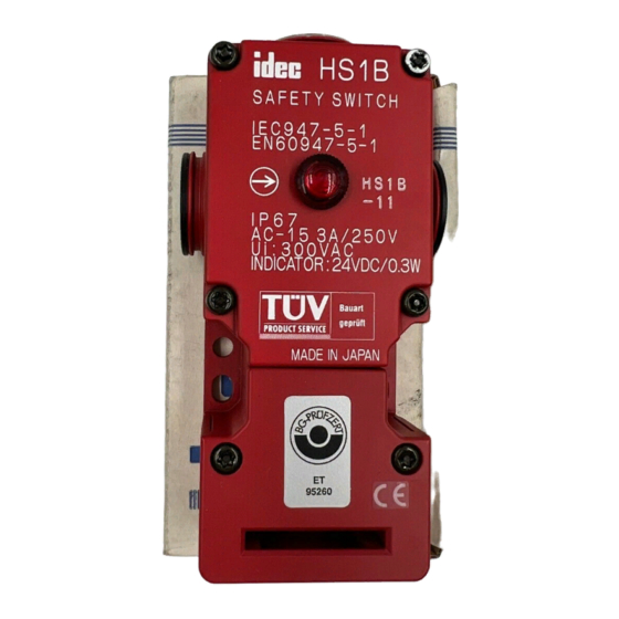
INSTRUCTION SHEET - HS1C Series
INSTRUCTION SHEET
Original Instructions
Solenoid Type Safety Switch
HS1C Series
Thank you for purchasing this IDEC product. Confirm that the delivered product is
what you have ordered. Read this instruction sheet to make sure of correct operation.
S A F E T Y P R E C A U T I O N S
In this operation instruction sheet, safety precautions are categorized in order of
importance to Warning and Caution :
WARNING
Warning notices are used to emphasize that improper operation may cause severe
personal injury or death.
CAUTION
Caution notices are used where inattention might cause personal injury or damage to
equipment.
1
Type
HS1C-R144R- R
Solenoid unit mounting position
R : Right side
[ L ] : Left side
Circuit Diagram No.
Main Circuit
Auxiliary Circuit
blank : 1NC+1NC
1NO/1NO
1 : 1NC+1NC
1NO
2 : 1NC+1NC
1NC+1NC
3 : 1NC+1NC
1NC
2
Specifications and Ratings
Applicable Standards
EN ISO / ISO14119
IEC60947-5-1, EN60947-5-1
GS-ET-19, UL508
CSA C22.2 No.14, GB14048 5
Standards for Use
IEC60204-1/ EN60204-1
Applicable Directives
Low Voltage Direc ive, Machinery Directive
Operating Temperature
Operating Condition
Operating Humidity
Pollution Degree
Al itude
Inpulse withstand voltage ‹Uimp›
4kV (Between ground and LED, solenoid circuit : 2.5kV)
Raed Insulation voltage ‹Ui›
300V (Between ground and LED, solenoid circuit : 60V)
Thermal Current ‹Ith›
Main Circuit : 10A, Auxiliary Circuit : 3A
Contact Ra ings
(Reference Values)
‹Ue , Ie›
Main
Circuit
Auxiliary
Circuit
Class of Protection
Class I ( EC61140) *2
Operating Frequency
900 operations/hour
Operating Speed
0.05 to 1.0 m/s
B10d
2,000,000 (EN ISO 13849-1 Annex C Table C.1)
Mechanical Durability
1,000,000 operations min. (GS-ET-19)
Electrical Durability
100,000 opera ions min. (AC-12 250V•6A)
1,000,000 operations min. (AC/DC 24V 100mA)
(900 operations / hour)
Damage Limits : 1,000m/s
Shock Resistance
Vibration Resistance
Operating Extremes :10 to 55Hz, half amplitude 0.5mm
Damage Limits : 30Hz, half amplitude 1.5mm
Actuator Tensile Strength
Fzh=1,500N minimum
when Locked
F1max.=1,950N minimum (GS-ET-19) *3, *4
Direct Opening Travel
11 mm minimum
Direct Opening Force
20 N minimum
Contact Resistance
100 mΩ maximum (Ini ial value)
Degree of Protection
IP67 (IEC60529)
Indicator Color
G : Green
R : Red
Housing Color
R : Red
LED voltage
4 : DC24V
[ 0 ] : Without LED
Solenoid voltage
4 : DC24V
*1 Type Nos. in [ ] are not supplied as
standard. Contact IDEC if required.
-25 to +50°C (no freezing)
45 to 85%RH (no condensation)
3
2,000m maximum
30V
125V
A
Resistive load (AC-12)
10A
10A
C
Induc ive load (AC-15)
10A
5A
D
Resistive load (DC-12)
6A
-
C
Induc ive load (DC-13)
3A
0.9A
A
Resistive load (AC-12)
-
3A
C
Induc ive load (AC-15)
-
-
D
Resistive load (DC-12)
3A
-
C
Induc ive load (DC-13)
3A
0.9A
2
Solenoid Type Safety Switch
Cont ct Resistance
g
Conditional short circuit current
Short-Circuit Protective Device
Rated Operating Voltage
Rated Current
Turn ON Voltage
Turn OFF Voltage
Rated Power Consumption
Rated Operating Voltage
Rated Current
Light Source
Illumination Color
Ratings approved by safety agencies
(1) TÜV rating
AC-15 250V, 3A
*2 Basic insulation of 4kV impulse withstand voltage is ensured between different
contact circuits and between contact circuits and LED or solenoid in the enclosure.
When both SELV (safety extra low voltage) or PELV (protective extra low voltage)
circuits and other circuits (such as 230V AC circuits) are used for the solenoid
power and contact circuits at the same time, the SELV or PELV requirements are
not met any more.
*3 The actuator locking strength is rated at 1,500N of static load. Do not apply a load
higher than the rated value. When a higher load is expected to work on the
actuator, provide an additional system consisting of another safety switch without
lock (such as the HS5D safety switch) or a sensor to detect door opening and stop
the machine.
*4 F1max. is maximum force. The actuator's guard-locking force Fzh is calculated in
accodance with GS-ET-19 :
maximum force (F1max.)
Fzh =
Safety coefficient (=1.3)
3
Mounting Examples
• Install the interlock switch on the immovable machine or guard, and install the
actuator on the movable door. Do not install both interlock switch and actuator on
the movable door, otherwise he angle of insertion of the actuator to he safety switch
may become inappropriate, and failure will occur.
(Examples of Mounting on Sliding Doors)
Door
Safety
Switch
HS9Z-A1
Actuator
Lock
Door Stop
Minimum Radius of Hinged Door
When using the safety switch for a hinged door, the minimum radius of the applicable
door is shown in the following figures.
When he center of the hinged door is on
the extension line of he actuator
mounting surfase.
• L-shaped actuator : HS9Z-A2
250V
6A
3A
-
-
3A
3A
Door Hinge
-
-
• Adjustable actuator : HS9Z-A3
CAUTION
The figures shown above are based on the condition that the actuator enters and
exits the actuator entry slot smoothry when the door is closed or opened. Since
there may be deviation or dislocation of the hinged door, make sure of correct
operation in the actual application before installation.
100A(250V)
250V AC,10A fast acting type fuse
24VDC
415mA
Rated Voltage × 85% maximum (at 20°C)
Rated Voltage × 10% minimum (at 20°C)
Approx. 10W
24VDC
10mA
LED lamp
R(Red), G(Green) (Φ12Lens)
(2) UL, c-UL rating
(3) CCC rating
3A, 250V ac, General Use
3A, 30V dc, Resistive
(Examples of Mounting on Hinged Doors)
HS9Z-A2
Actuator
Safety
Switch
When the center of the hinged door is on
the extension line of the contact surface
of actuator and safety switch.
Door Hinge
Door Hinge
Door Hinge
2016.08
B-1909-1(0)
AC-15 250V, 3A
DC-13 125V, 0.9A
Hinged
Door
Latch
HS9Z-A1
Actuator
Door Hinge
Door Hinge
Advertisement

Related Manuals for IDEC HS1C Series


Summary of Contents for IDEC HS1C Series
- Page 1 LED lamp Illumination Color R(Red), G(Green) (Φ12Lens) Thank you for purchasing this IDEC product. Confirm that the delivered product is what you have ordered. Read this instruction sheet to make sure of correct operation. Ratings approved by safety agencies (1) TÜV rating...
- Page 2 INSTRUCTION SHEET - HS1C Series 2016.08 Solenoid Type Safety Switch B-1909-1(0) Actuator Mounting Reference Position Precautions for Operation • As shown below, the mounting reference position of the actuator inserted into the safety switch is the actuator cover or stop film touches the safety switch ligh ly. (After Installation mounting the actuator, remove the actuator cover or stop film from the safety switch.)
-
Page 3: Contact Operation
INSTRUCTION SHEET - HS1C Series 2016.08 Solenoid Type Safety Switch B-1909-1(0) Contact Operation Wiring Contact Configuration Wire Length inside the Safety Switch Type Contact Configuration *7 Screw Through Conduit Hole Terminal Indicator Door monitor Lock monitor 30±2 45±2 70±2 30±2 50±2 65±2... - Page 4 INSTRUCTION SHEET - HS1C Series 2016.08 Solenoid Type Safety Switch B-1909-1(0) Example of wiring Diagram realizing Safety Category Example of a circuit diagram for Safety Category 3 Example of a circuit diagram for Safety Category 4 (attainable PL = d)
- Page 5 INSTRUCTION SHEET - HS1C Series 2016.08 Solenoid Type Safety Switch B-1909-1(0) Accessories dimensions Dimensions (mm) Type : HS9Z-A1 (58.3) Safety Switch dimensions □ □ 47 3 Type : HS1C-R 44R- 19.3 39.7 2-M6 Mounting Hole Layout Actuator cover (supplied) Type : HS9Z-A2 (41.5)