SeaLevel DIO-16.PCI User Manual
Hide thumbs
Also See for DIO-16.PCI:
- User manual (19 pages) ,
- User manual (23 pages) ,
- User manual (23 pages)

Related Manuals for SeaLevel DIO-16.PCI


Summary of Contents for SeaLevel DIO-16.PCI
- Page 1 DIO-16.PCI User Manual | 8002H © Sealevel Systems, Inc. 8002H Manual | SL9021 9/2021...
-
Page 2: Table Of Contents
CONTENTS ............................................2 INTRODUCTION ........................................... 3 BEFORE YOU GET STARTED ......................................4 SOFTWARE INSTALLATION ....................................... 6 HARDWARE INSTALLATION ....................................... 7 PROGRAMMING THE DIO-16.PCI ....................................8 ELECTRICAL CHARACTERISTICS ....................................14 SPECIFICATIONS ..........................................15 EXAMPLE CIRCUITS .......................................... 17 APPENDIX A – TROUBLESHOOTING ..................................... 18 APPENDIX B –... -
Page 3: Introduction
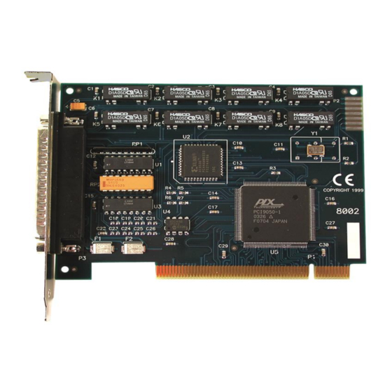
Introduction Overview The DIO-16.PCI provides 8 optically isolated inputs and 8 reed relay outputs. The inputs (rated for 10-30V) protect the PC and other sensitive equipment from spikes and ground loop current that can be generated in industrial environments, while the outputs provide high quality, long life, low current (10 Watt maximum), dry contact switch closures. -
Page 4: Before You Get Started
Before You Get Started What’s Included The DIO-16.PCI is shipped with the following items. If any of these items is missing or damaged, please contact Sealevel for replacement. • DIO-16.PCI Adapter Advisory Conventions Warning The highest level of importance used to stress a condition where damage could result to the product, or the user could suffer serious injury. - Page 5 Optional Items Depending upon your application, you are likely to find one or more of the following items useful for interfacing the DIO-16.PCI to real-world signals. All items can be purchased from our website (http://www.sealevel.com) or by calling (864) 843-4343.
-
Page 6: Software Installation
Software Installation For Windows Users Begin by locating, selecting, and installing the SeaIO software from the Sealevel website. The SeaIO Software Overview page provides information that will allow you to easily download the SeaIO Software for Windows. Other Operating Systems Refer to the appropriate section of the Serial Utilities Software. -
Page 7: Hardware Installation
Replace the screw you removed for the blank and use it to secure the adapter into the slot. (This is required to ensure FCC Part 15 compliance.) Replace the cover. Connect the power cord The DIO-16.PCI is now ready for use. © Sealevel Systems, Inc. 8002H Manual | SL9021 9/2021... -
Page 8: Programming The Dio-16.Pci
Digital I/O Interface The DIO-16.PCI provides two parallel input/output (I/O) ports. The ports are organized as ports A, B, C, and D. Port A is an input port interfaced to optically isolated inputs, while port C is the reed relay output port. - Page 9 Increasing the input resistor accordingly can increase the maximum input voltage. Because socketed DIP resistors are utilized, they can easily be replaced with a different value. Sealevel, if necessary, can do this. The input circuits are not intended for monitoring 120-volt AC circuits. In addition to being too high a voltage for the circuits, it is dangerous to have that high a voltage on the card.
- Page 10 Programming the DIO-16.PCI, Continued Input Port Pin Assignments (DB-37 Male) Port A Bit 2,20 3,21 4,22 5,23 6,24 7,25 8,26 9,27 Output Ports (Reed Relays) Reed relays provide very high quality, long life, low current (10 Watt maximum), dry contact switch closures.
- Page 11 Programming the DIO-16.PCI, Continued Direct Hardware Control In systems where the user’s program has direct access to the hardware (i.e., DOS) the table below gives the mapping and functions that the DIO-16.PCI provides. R = Read R/W = Read or Write...
- Page 12 Programming the DIO-16.PCI, Continued Register Description All ports are set to input after reset or power up. Address Mode Base+0 PAD7 PAD6 PAD5 PAD4 PAD3 PAD2 PAD1 PAD0 Base+1 Base+2 RD/WR PCD7 PCD6 PCD5 PCD4 PCD3 PCD2 PCD1 PCD0 Base+3...
- Page 13 Programming the DIO-16.PCI, Continued Interrupt Mode Select Table Interrupt source is Base+0 bit D0. When selecting the Interrupt Type, always disable interrupts prior to changing or setting states. This will help prevent inadvertent or unexpected interrupts from occurring. IRC1 IRC0...
-
Page 14: Electrical Characteristics
1 eight bit optically isolated input port • DB-37 Male connector • Highly reliable 10 VA DIP reed relays • Multiple adapters can reside in same computer • PCI 2.1 Bus compatible © Sealevel Systems, Inc. 8002H Manual | SL9021 9/2021... -
Page 15: Specifications
Contact Speed – Bounce .5 mS Maximum Operating Speed 600Hz Environmental Specifications Specification Operating Storage Temperature Range 0º to 70º C -50º to 105º C Power Consumption Supply Line +5 VDC Rating 280 mA © Sealevel Systems, Inc. 8002H Manual | SL9021 9/2021... - Page 16 3.9 inches (9.9 cm, including Gold fingers) Manufacturing All Sealevel Systems Printed Circuit boards are built to UL 94V0 rating and are 100% electrically tested. These printed circuit boards are solder mask over bare copper or solder mask over tin nickel.
-
Page 17: Example Circuits
Example Circuits Input Circuit Output Circuit © Sealevel Systems, Inc. 8002H Manual | SL9021 9/2021... -
Page 18: Appendix A - Troubleshooting
4. Use the SeaIO Control Panel applet or the Device Manager’s property page for card identification and configuration. If these steps do not solve your problem, please call Sealevel Systems’ Technical Support, (864) 843-4343. Our technical support is free and available from 8:00AM-5PM Eastern Time, Monday through Friday. For email support contact: support@sealevel.com. -
Page 19: Appendix B - How To Get Assistance
If possible, please have the adapter installed in a computer ready to run diagnostics. Sealevel Systems provides an FAQ section on its web site. Please refer to this to answer many common questions. This section can be found at http://www.sealevel.com/faq.asp. -
Page 20: Appendix - Silk Screen - 8002H Pcb
Appendix C – Silk Screen – 8002H PCB 3.90" 5.00" © Sealevel Systems, Inc. 8002H Manual | SL9021 9/2021... -
Page 21: Appendix D- Compliance Notices
Always use cabling provided with this product if possible. If no cable is provided or if an alternate cable is required, use high quality shielded cabling to maintain compliance with FCC/EMC directives. © Sealevel Systems, Inc. 8002H Manual | SL9021 9/2021... -
Page 22: Warranty
Sealevel's commitment to providing the best I/O solutions is reflected in the Lifetime Warranty that is standard on all Sealevel manufactured I/O products. We are able to offer this warranty due to our control of manufacturing quality and the historically high reliability of our products in the field. Sealevel products are designed and manufactured at its Liberty, South Carolina facility, allowing direct control over product development, production, burn-in and testing.
Need help?
Do you have a question about the DIO-16.PCI and is the answer not in the manual?
Questions and answers