
Related Manuals for SeaLevel DIO-16


Summary of Contents for SeaLevel DIO-16
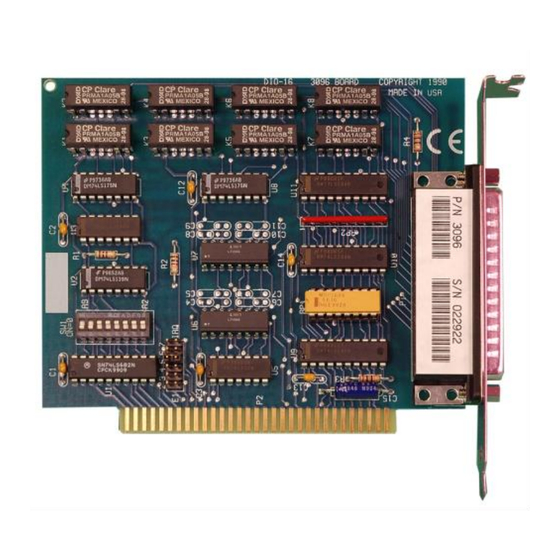
- Page 1 DIO-16 User Manual | 3096H © Sealevel Systems, Inc. 3096H Manual | SL9026H 7/2021...
-
Page 2: Table Of Contents
INTRODUCTION ..............................3 BEFORE YOU GET STARTED ..........................4 CARD SETUP ................................ 6 SOFTWARE INSTALLATION ..........................8 PHYSICAL INSTALLATION ..........................10 PROGRAMMING THE DIO-16 ..........................11 ELECTRICAL CHARACTERISTICS ........................17 SPECIFICATIONS ............................... 18 EXAMPLE CIRCUITS ............................19 APPENDIX A – TROUBLESHOOTING........................ 20 APPENDIX B –... -
Page 3: Introduction
Introduction The DIO-16 provides 8 optically isolated inputs and 8 reed relay outputs. The inputs (rated for 10-30V) protect the PC and other sensitive equipment from spikes and ground loop current that can be generated in industrial environments, while the outputs provide high quality, long life, low current (10 Watt maximum), dry contact switch closures. -
Page 4: Before You Get Started
Before You Get Started What’s Included The DIO-16 is shipped with the following items. If any of these items are missing or damaged, please contact Sealevel for replacement. • DIO-16 Adapter Advisory Conventions Warning The highest level of importance used to stress a condition where damage could result to the product, or the user could suffer serious injury. - Page 5 Optional Items Depending upon your application, you are likely to find one or more of the following items useful for interfacing the DIO-16 to real-world signals. All items can be purchased from our website (www.sealevel.com) or by calling (864) 843-4343.
-
Page 6: Card Setup
The DIO-16 contains several jumper straps for each port that must be set for proper operation. Address Selection The DIO-16 occupies 4 consecutive I/O locations. The DIP-switch (SW1) is used to set the base address for these locations. Be careful when selecting the base address as some selections conflict with existing PC ports. - Page 7 2/9 through 7 (IRQ 2/9 - 7) can be selected by placing the jumper in the appropriate position. Other inputs can be ‘wire OR ed.’ to also generate interrupts if desired. Please consult the factory for more information. IRQ Header E2 © Sealevel Systems, Inc. 3096H Manual | SL9026H 7/2021...
-
Page 8: Software Installation
After accomplishing the above steps, bring up the Control Panel and double-click on the SeaIO Devices icon. To install a new card, click "Add Port". Repeat this procedure for as many SeaIO cards as you wish to install. © Sealevel Systems, Inc. 3096H Manual | SL9026H 7/2021... - Page 9 8. The driver has enabled the card and is ready to use. To set up Linux to automatically load the driver; refer to a Linux manual concerning your specific distribution for help. © Sealevel Systems, Inc. 3096H Manual | SL9026H 7/2021...
-
Page 10: Physical Installation
Replace the screw you removed for the blank and use it to secure the adapter into the slot. (This is required to ensure FCC Part 15 compliance.) Replace the cover. Connect the power cord The DIO-16 is now ready for use. © Sealevel Systems, Inc. 3096H Manual | SL9026H 7/2021... -
Page 11: Programming The Dio-16
/ removal of the software and information about latency, logic states, and device configuration. For C language programmers we recommend using the API to access the DIO-16. If you are programming in Visual Basic, using the ActiveX control included with SeaI/O is advised. - Page 12 Digital I/O Interface The DIO-16 provides two parallel input/output (I/O) ports. The ports are organized as ports A, B, C, and D. Port A is an input port interfaced to optically isolated inputs, while port C is the reed relay output port. Ports B and C are unused.
- Page 13 Increasing the input resistor accordingly can increase the maximum input voltage. Because socketed DIP resistors are utilized, they can easily be replaced with a different value. Sealevel, if necessary can do this. The input circuits are not intended for monitoring 120-volt AC circuits. In addition to being too high a voltage for the circuits, it is dangerous to have that high a voltage on the card.
- Page 14 Programming the DIO-16, Continued Output Port Pin Assignments Port C Bit Relay P2 Pin 10,28 11,29 12,30 13,31 14,32 15,33 16,34 17,35 Power and Ground Pin Assignments Ground 18,36,37 + 5 Volts + 12 Volts Relative Addressing vs. Absolute Addressing The SeaIO API makes a distinction between “absolute”...
- Page 15 The relay ports return the ones complement of the value that is currently being used to drive the relays. Writing the Outputs The output ports are the only ports that can be written. The relays on a standard DIO-16 are normally open. To close a relay a one must be written to the appropriate bit.
- Page 16 Programming the DIO-16, Continued Interrupt Control When enabled, interrupts are generated on Port A bit D0. IRQEN Interrupt enable 1 = enabled 0 = disabled ( 0 on power up ) IRC0 Interrupt mode select, see table below IRC1 Interrupt mode select, see table below Interrupt Mode Select Table Interrupt source is Base+0 bit D0.
-
Page 17: Electrical Characteristics
1 eight bit optically isolated input port • Highly reliable 10 VA DIP reed relays • Multiple adapters can reside in same computer • All address, data and control signals are TTL compatible © Sealevel Systems, Inc. 3096H Manual | SL9026H 7/2021... -
Page 18: Specifications
4.2” (10.7 cm, including Gold fingers) Manufacturing All Sealevel Systems Printed Circuit boards are built to UL 94V0 rating and are 100% electrically tested. These printed circuit boards are solder mask over bare copper or solder mask over tin nickel. -
Page 19: Example Circuits
Example Circuits Input Circuit Output Circuit © Sealevel Systems, Inc. 3096H Manual | SL9026H 7/2021... -
Page 20: Appendix A - Troubleshooting
• 2E8-2EF is typically reserved for COM4: If these steps do not solve your problem, please call Sealevel Systems’ Technical Support, (864) 843-4343. Our technical support is free and available from 8:00 AM-5:00 PM Eastern Time Monday through Friday. For email support contact support@sealevel.com. -
Page 21: Appendix B - How To Get Assistance
When calling for technical assistance, please have your user manual and current adapter settings. If possible, please have the adapter installed in a computer ready to run diagnostics. Sealevel Systems provides an FAQ section on its web site. Please refer to this to answer many common questions. This section can be found at http://www.sealevel.com/faq.asp. -
Page 22: Appendix C - Silk Screen - 3096H Pcb
Appendix C – Silk Screen - 3096H PCB 4.2" 4.9" 3.9" © Sealevel Systems, Inc. 3096H Manual | SL9026H 7/2021... -
Page 23: Appendix D - Compliance Notices
Always use cabling provided with this product if possible. If no cable is provided or if an alternate cable is required, use high quality shielded cabling to maintain compliance with FCC/EMC directives. © Sealevel Systems, Inc. 3096H Manual | SL9026H 7/2021... -
Page 24: Warranty
Sealevel's commitment to providing the best I/O solutions is reflected in the Lifetime Warranty that is standard on all Sealevel manufactured I/O products. We are able to offer this warranty due to our control of manufacturing quality and the historically high reliability of our products in the field. Sealevel products are designed and manufactured at its Liberty, South Carolina facility, allowing direct control over product development, production, burn-in and testing.
Need help?
Do you have a question about the DIO-16 and is the answer not in the manual?
Questions and answers