SeaLevel DIO-32.PCI User Manual
Digital i/o interface
Hide thumbs
Also See for DIO-32.PCI:
- User manual (18 pages) ,
- User manual (24 pages) ,
- User manual (15 pages)

Related Manuals for SeaLevel DIO-32.PCI


Summary of Contents for SeaLevel DIO-32.PCI
- Page 1 DIO-32.PCI User Manual | 8004 © Sealevel Systems, Inc. 8004 Manual | SL9022 9/2021...
-
Page 2: Table Of Contents
Contents CONTENTS ............................................2 INTRODUCTION ........................................... 3 BEFORE YOU GET STARTED ......................................4 INSTALLATION ............................................. 5 PROGRAMMING THE DIO-32.PCI ..................................... 7 ELECTRICAL CHARACTERISTICS ....................................15 SPECIFICATIONS ..........................................16 EXAMPLE CIRCUITS ......................................... 18 APPENDIX A – TROUBLESHOOTING ..................................... 19 APPENDIX B – HOW TO GET ASSISTANCE.................................. 20 APPENDIX C –... -
Page 3: Introduction
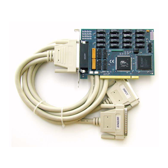
Introduction Overview The DIO-32.PCI digital I/O interface provides 16 optically isolated inputs and 16 reed relay outputs. The inputs (rated for 3-13V) protect the PC and other sensitive equipment from spikes and ground loop current that can be generated in industrial environments, while the outputs provide high quality, long life, low current (10 Watt maximum), dry contact switch closures. -
Page 4: Before You Get Started
Before You Get Started What’s Included The DIO-32.PCI is shipped with the following items. If any of these items are missing or damaged, please contact Sealevel for replacement. • Item# 8004 – DIO-32.PCI Adapter • Item# CA165 – DB-78 Male to DB-37 Male and DB-37 Female V-cable... -
Page 5: Installation
Linux releases. Also included is a series of files explaining proper Linux syntax and typical Linux serial implementations. For additional software support, please call Sealevel Systems’ Technical Support, (864) 843-4343. Our technical support is free and available from 8:00AM-5PM Eastern Time, Monday through Friday. For email support contact: mailto:support@sealevel.com. - Page 6 Replace the screw you removed for the blank and use it to secure the adapter into the slot. (This is required to ensure FCC Part 15 compliance.) Replace the cover. Connect the power cord Installation is finished. © Sealevel Systems, Inc. 8004 Manual | SL9022 9/2021...
-
Page 7: Programming The Dio-32.Pci
/ removal of the software and information about latency, logic states, and device configuration. For C language programmers we recommend using the API to access the DIO-32.PCI. If you are programming in Visual Basic, using the ActiveX control included with SeaI/O is advised. - Page 8 PROGRAMMING THE DIO-32.PCI, CONTINUED Digital I/O Interface The DIO-32.PCI provides four parallel input/output (I/O) ports. The ports are organized as ports A, B, C, and D. Port A and B are input ports interfaced to optically isolated inputs, while ports C and D are reed relay output ports.
- Page 9 The turn-off voltage for all resistors is less than 1V. Increasing the input resistor accordingly can increase the maximum input voltage. Because socketed DIP resistors are utilized, they can easily be replaced with a different value. Sealevel can do this, if necessary.
- Page 10 PROGRAMMING THE DIO-32.PCI, CONTINUED The CA165 cable input pin out is not compatible with the 3093 ISA digital I/O board. If you are upgrading from the 3093 and wish to preserve existing infrastructure wiring, order the CA378 cable. Output Ports (Reed Relay) Reed relays provide very high quality, long life, low current (10 Watt maximum), dry contact switch closures.
- Page 11 39,57,58 18,36,37 +12V Direct Hardware Control In systems where the user’s program has direct access to the hardware (DOS) the tables that follow give the mapping and functions that the DIO-32.PCI provides. Function Available Port Address Hex Port Type Base + 0...
- Page 12 The relay ports return the ones complement of the value that is currently being used to drive the relays. Writing the Outputs The output ports are the only ports that can be written. The relays on a standard DIO-32.PCI are normally open. To close a relay a one must be written to the appropriate bit.
- Page 13 PROGRAMMING THE DIO-32.PCI, CONTINUED Interrupt Mode Select Table Interrupt source is Base+0 bit D0. When selecting the Interrupt Type, always disable interrupts prior to changing or setting states. This will help prevent inadvertent or unexpected interrupts from occurring. IRC1 IRC0...
- Page 14 PROGRAMMING THE DIO-32.PCI, CONTINUED CA378 Input Pin Assignments (DB-37 Female) Inputs are interfaced via the DB-37 female connector on the optional CA378 cable. Port A Bit Port A Pins Port B Bit Port B Pins 18,37 10,29 17,36 9, 28...
-
Page 15: Electrical Characteristics
• DB-37 Male connector for relay outputs • DB-37 Female connector for optically isolated inputs • Highly reliable 10 VA DIP reed relays • Multiple adapters can reside in same computer © Sealevel Systems, Inc. 8004 Manual | SL9022 9/2021... -
Page 16: Specifications
-50º to 105º C Manufacturing All Sealevel Systems Printed Circuit boards are built to UL 94V0 rating and are 100% electrically tested. These printed circuit boards are solder mask over bare copper or solder mask over tin nickel. Power Requirements... - Page 17 SPECIFICATIONS, CONTINUED Physical Dimensions Board length 5.00 inches (12.700 cm) Board Height including Goldfingers 3.90 inches (9.906 cm) © Sealevel Systems, Inc. 8004 Manual | SL9022 9/2021...
-
Page 18: Example Circuits
Example Circuits Input Circuit Output Circuit © Sealevel Systems, Inc. 8004 Manual | SL9022 9/2021... -
Page 19: Appendix A - Troubleshooting
Appendix A – Troubleshooting Sealevel Software is supplied with the Sealevel Systems adapter and will be used in the troubleshooting procedures. By using this software and following these simple steps, most common problems can be eliminated without the need to call Technical Support. -
Page 20: Appendix B - How To Get Assistance
If possible, please have the adapter installed in a computer ready to run diagnostics. Sealevel Systems provides an FAQ section on its web site. Please refer to this to answer many common questions. This section can be found at http://www.sealevel.com/faq.asp. -
Page 21: Appendix C - Silk Screen - 8004 Pcb
Appendix C – Silk Screen – 8004 PCB 4.200" 6.00" 3.825" © Sealevel Systems, Inc. 8004 Manual | SL9022 9/2021... -
Page 22: Appendix D - Compliance Notices
Always use cabling provided with this product if possible. If no cable is provided or if an alternate cable is required, use high quality shielded cabling to maintain compliance with FCC/EMC directives. © Sealevel Systems, Inc. 8004 Manual | SL9022 9/2021... -
Page 23: Warranty
Sealevel's commitment to providing the best I/O solutions is reflected in the Lifetime Warranty that is standard on all Sealevel manufactured I/O products. We are able to offer this warranty due to our control of manufacturing quality and the historically high reliability of our products in the field. Sealevel products are designed and manufactured at its Liberty, South Carolina facility, allowing direct control over product development, production, burn-in and testing.
Need help?
Do you have a question about the DIO-32.PCI and is the answer not in the manual?
Questions and answers